14F-6, No. 79, Sec. 1, Xintai 5th Rd, Xizhi Dist., New Taipei City, 22101 Taiwan (R.O.C.)
Tel: 886-2-2698-3877
Fax: 886-2-2698-4089
email : [email protected]

Selection
MICROTEST stator testing solution can be tailored into a complete testing system based on different requirements. Firstly, you can evaluate whether to opt for a rack-mounted or desktop configuration, as well as whether to incorporate PC connectivity.
| System | Benchtop | Rack |
|
|
 |
| Evaluate whether to include PC connectivity software. | ||
| Function | Operate directly on the instrument | PC Link |
| Production Traceability Management - Implementing Bar Code/Label Printer/Laser Engraver | / | ● |
| Store test file sets |
100 sets (existing instruments) |
Unlimited (according to PC memory) |
| Sharing test files between devices |
Unable to share, recreate the file |
Share through PC software |
| Accessing test data | / |
Transfer test data to the PC via the RS-232 interface |
| Uploading test data to a cloud database | / | ● |
| User Permission Management" or "User Access Control |
/
|
Supports permission management, configuration through Engineering Mode |
| CPK Report |
/
|
|
| Customized CPK Report According to Customer Requirements | / |  |
SPEC
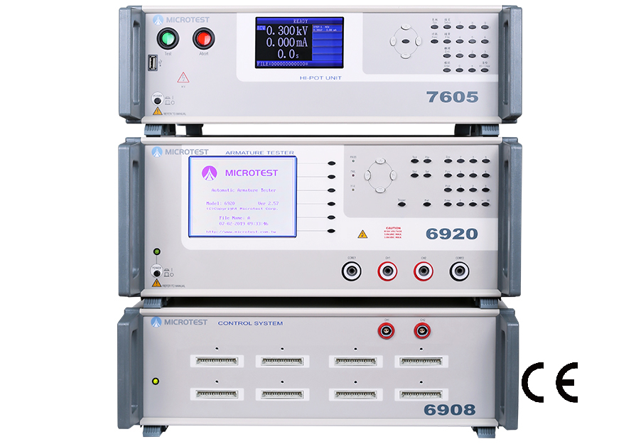
| Model | MT-6920 |
| Test Channel | 24/48 |
| DC Resistance Test (6920) | |
| DCR Range | 0.1mΩ-100kΩ |
| Measuring Mode | 4-Wire |
| DCR Accuracy |
Low Resistance 0.1mΩ-1Ω±(0.2%±1mΩ) High Resistance 1Ω-100KΩ±0.1% |
| Safety Hi pot Test (7605) | |
| AC Output Voltage | 100V-3000V |
| AC Leakage Current | 0.001mA-10mA |
| AC Arcing Detection | Detect gears from 0-9 |
| DC Output Voltage | 100V-3000V |
| DC Leakage Current | 0.001mA-5mA |
| DC Arcing Detection | Detect gears from 0-9 |
| IR Output Voltage | 100V-1000V |
| Insulation Resistance | 1-9999MΩ |
| Measuring Time | 0.1-99.9s Continuously adjustable |
| Voltage Accuracy | ±(3% of setting+5V) |
| Impulse Winding Test (6920) | |
| Impulse Voltage (programmable) | 200V-3000V |
| Impulse Voltage Accuracy | ±2% |
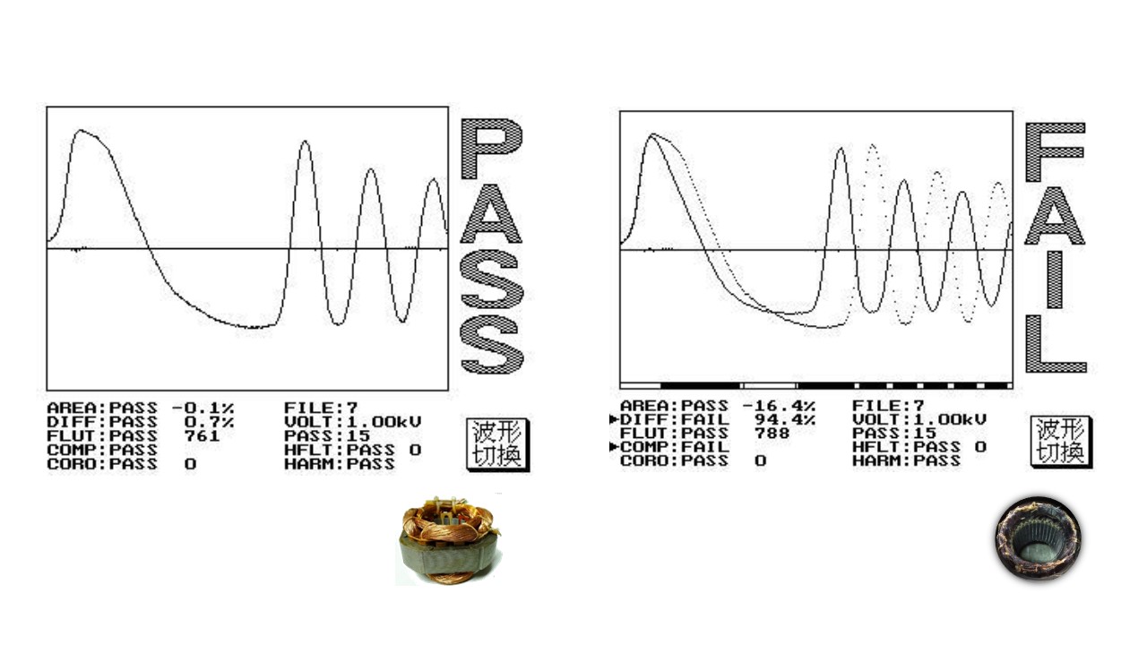
| Total area comparison |
When layer short happened, the loss of power on coil increase, the resonance damping coefficient increase, resonance amplitude decrease, the total area decrease. These are the basic parameters we check layer short. By calculating and comparing the deference of area between golden sample and DUT. |
| Differential area comparison |
Add up the difference between normal wave and DUT wave call “ Area differential”. By calculating and comparing the deference of area between golden sample and DUT. To determine the degree of waveform overlap. |
| Wave comparison | Set a acceptable wave range, if the DUT’s wave is in this range shows “pass” otherwise, “fail” This parameter can judge both amplitude and phase of resonance wave. This can increase the detection capability of layer short. |
| Corona comparison | In pulse test, the insulation defect will cause discharge and create corona. This function is able to count the times that corona happened base on the degree of deviation. Detect the discharge phenomenon on the coil. |
| Flat comparison | If the layer short happened, the waveform will tremble. Therefore, the instrument will quantize and compared it. |
SYSTEM
| Test fixture | According to the test requirements | |
| Indicator | Pass/Fail Screen Diaplay/Sound | |
| Built-in Storage | Storage of 100 rewritable data sets | |
| Operation | Manual, RS-232 | |
| Power Supply | Voltage | 90-132Vac or 198-264Vac |
| Frequency | 50/60Hz | |
| Power consumption | 300VA | |
| Environment | Temperature | 10℃-40℃ |
| Humidity | 20-90%RH | |
| Display | 6920 | 5.7" dot-matrix display (320*240) |
| 7605 | 4.3" TFT LCD (480*272) | |
|
Dimension (W*H*D) |
6920 | 435x190x522mm |
| 7605 | 435x145x522mm | |
| 6908 | 435x145x522mm | |
| Weight | 6920 | 15 Kg |
| 7605 | 14 Kg | |
| 6908 | 7 Kg | |
| Interface | RS-232 | |
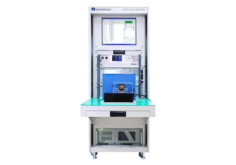
MT-6920 モーターローター試験システム
システムはモーターステータコイルにワンストップでの電気試験システムを提供します。
モーター動作の原因となる2つの部品はステータコイル+ロータコイルです。
ステータの構造
ステータは周囲の磁界を固定部に供給します。ステーターは、導電性のコイルにリング状の磁性体を巻き付けたもので、対向するローターの上に精密に配置され、電流を通してクロスセンシングすることでローターを回転させます。
ロータの構造
磁性体は複数のフラップに分割され、分離されたシャフトによってシャフトの周りに固定されており、硬磁性体と軟磁性体に分類されます。
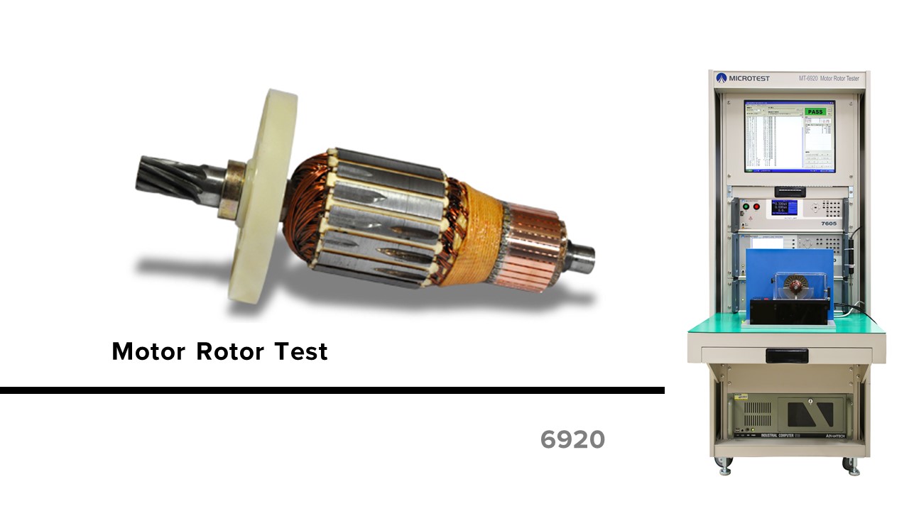
MT-6920は24/48セットの試験チャネルを提供します。
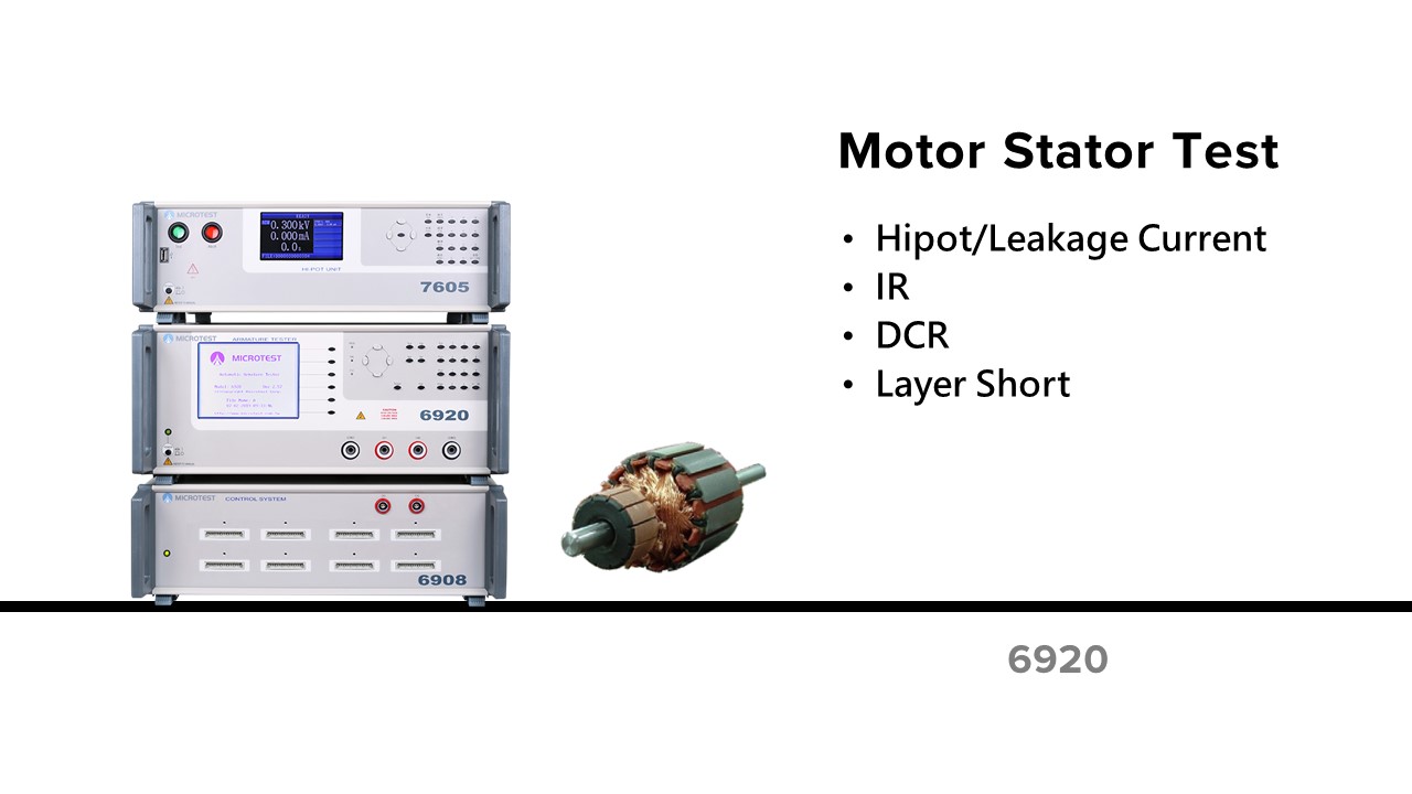
MT-6920 安全規格の耐圧試験は下記の試験項目:
コイルのターン間での短絡問題を認識する。
これは、磁気素子の同じ巻線が何ターンもの線で構成されていることであり、絶縁状態が良くないと、重ねられたコイル間でショートしてしまいます。つまり、巻線の一部が直接ショートしてしまい、インダクタとしての役割を果たせない場合で、磁界が異なる非対称な状態になり、残りのコイルに大きな電流が流れることになります。もし、モーターの動作中に発生すると、振動が大きくなり、電流が増加して出力が低下します。
コイルのターン間での短絡はどうやって発生しますか。
ターン間のショートによって、製品に対してどんな危険が発生しますか?(例えば:モーター)
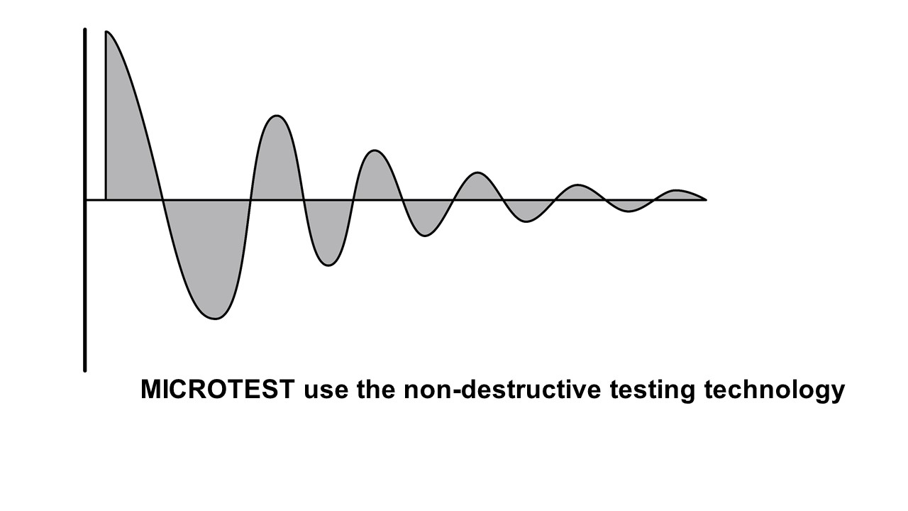
『パルス電圧と波形の比較』によって、巻線コイルのターン間短絡の測定します。
このパルス電圧は、巻線コイルの両端に非破壊・過渡的に電圧をかけて、被測定物の巻線コイルを傷つけずに電気特性を検出し、標準的な品質の標準コイルと被測定物のコイルとの「瞬間の波形」を通して品質を判断するものです。
瞬間の波形:コイル内部で発生したdamped sine waveを減衰させます。
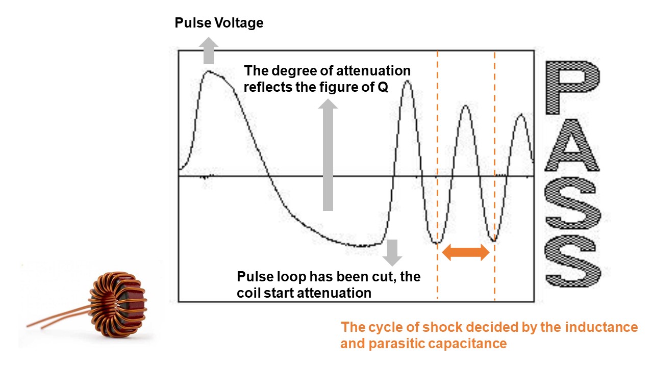
ターン間で短絡が発生した不良品は標準品とは波形が異なり、その波形の違いが不良品の電気的特性の変化を反映しています。
変更された電気特性は下記のとおりです。
MICROTEST 6920提供
共鳴波で覆われた面積を「総面積」と呼びます。 コイルのターン間で短絡が発生すると、コイルのエネルギー損失が増加し、共振減衰係数が増加し、共振振幅が減少し、総面積が減少するので、不良のコイルのエネルギー損失の差を比較します。
標準波形とテストする波形の差を合計して「面積差」と呼びます。 コイルのターン間で短絡が発生すると、インダクタンスが小さくなり、共振波形の位相角が変化によって、面積差が変化し、不良コイルのインダクタンスの違いを比較することができます。
基準波形を許容範囲内に設定することで、共振波形の振幅と位相を同時に把握することができ、ターン間の短絡を検出する能力が高まります。
高電圧パルス試験でモーターコイルが自身の絶縁システムによって損傷した場合、放電曲線を見るとコロナが発生します。
巻線コイルにターン間で放電が発生すると、波形データに隠れる数値の不連続性(すなわちノイズ)のみを数値化することができ、わかりやすい放電成分の判断を行うことができます。
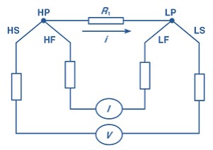
四線式DCR測定(温度補償)を提供します。
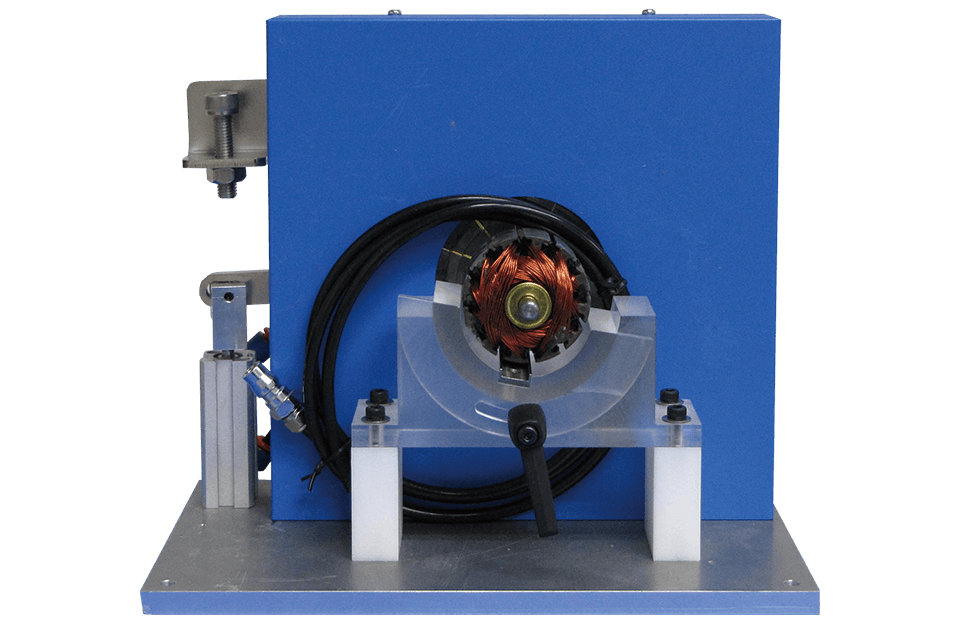
カスタマイズフィクスチャ
Standard Accessories
| Power Cord | |
| HV Test Cable | |
| Banana Plug Cable | |
| RCA adapter (Temperature Test Prob) | 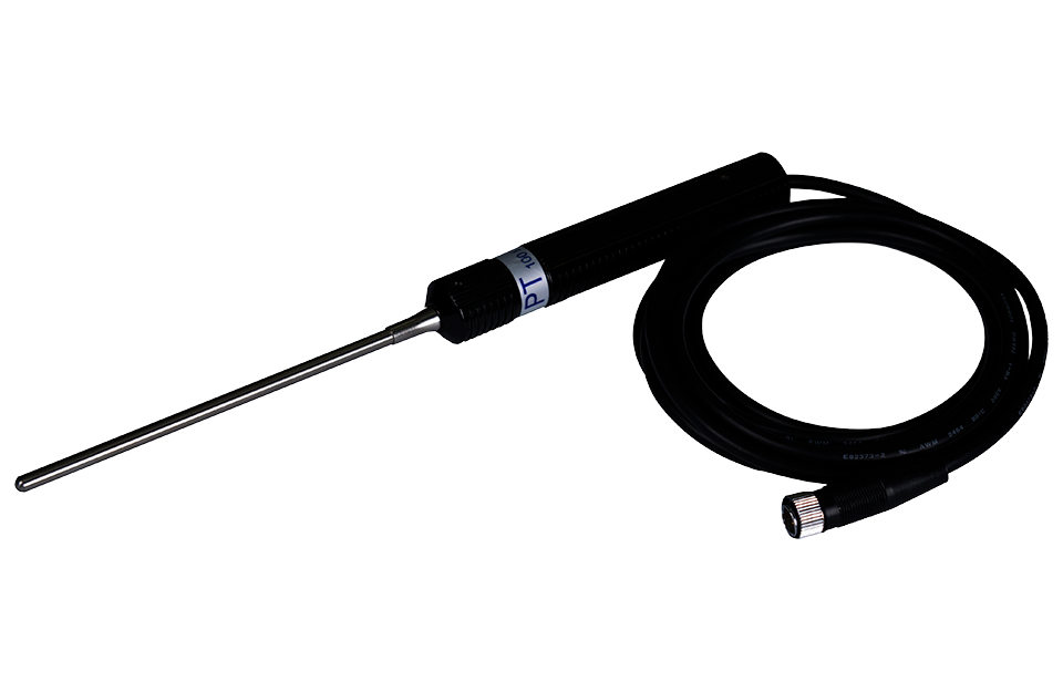 |
| RS-232 Cable | |
| D-Sub footswitch (F760001) | |
Optional Accessories
| PC Link Software | |
| Customized cabinet | |
| Test Fixture |  |