14F-6, No. 79, Sec. 1, Xintai5th Rd, XizhiDist., New Taipei City, 22101 Taiwan (R.O.C.)
Tel: 886-2-2698-3877
Fax: 886-2-2698-4089
email : [email protected]


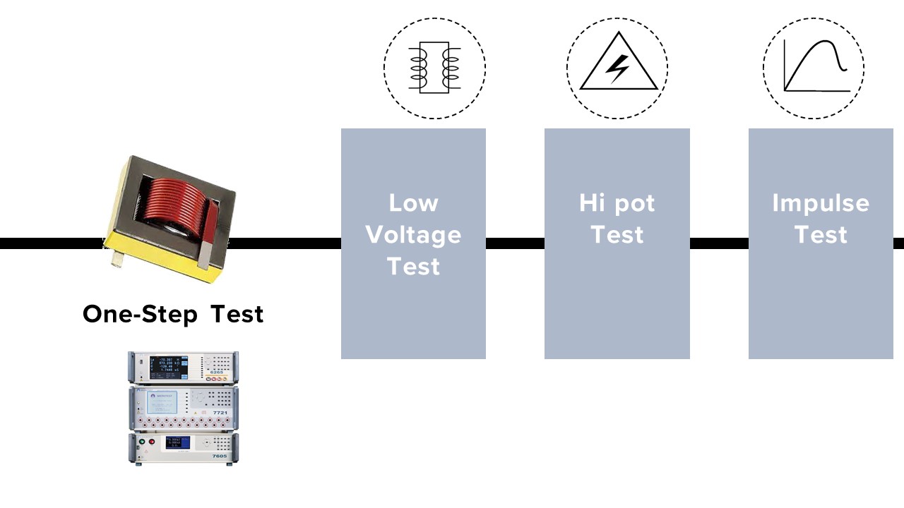
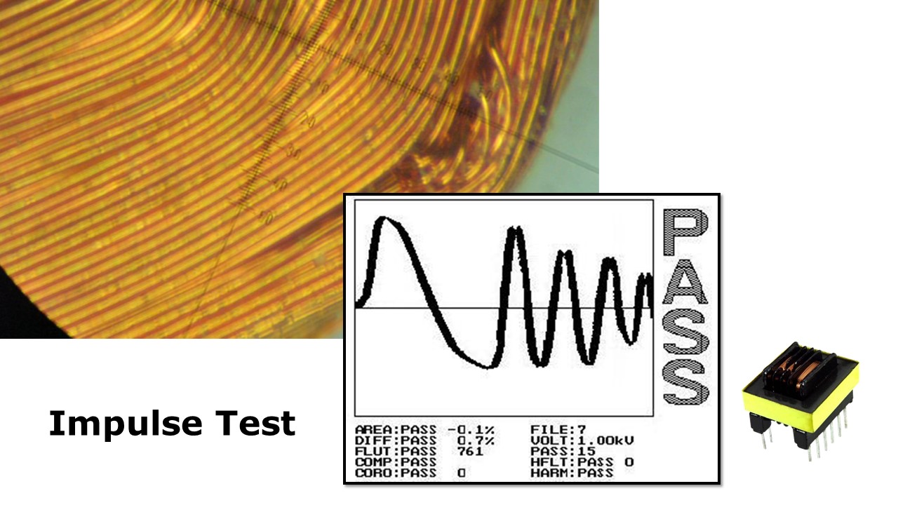
MICROTEST 3-in-1 トランス統合試験システムは、低電圧電気特性試験、安全性適合試験およびインパルス巻線試験を一体化した総合的なソリューションです。20チャネルの試験が可能であり、低電圧試験(インダクタンス、漏れインダクタンス、抵抗、静電容量などを含む)と、AC/DC耐電圧絶縁試験(最大5,000V/6,000V)を統合しています。これにより、トランス製品の効率的かつ便利な試験を実現します。インパルス巻線試験は、非破壊の高電圧パルス試験技術を用いており、L/C共振によって発生する減衰波形を解析することで、トランス巻線間または絶縁層間の短絡欠陥を検出します。
トランスのインダクタンス値を測定するには、200kHz、500kHz、1MHzの試験周波数が選択可能なLCRメーターをご使用ください。また、PC接続に対応したソフトウェアを利用することで、試験データの保存が可能です。
仕様
| 型名 |
3-in-1 (626X+7605+7721) |
|||||
| テストチャンネル |
20 |
|||||
| Low Voltage Electrical Test | ||||||
| 型名 | 6265 | 6266 | 6267 | |||
| 周波数 | 10Hz-200kHz | 10Hz-500kHz | 10Hz-1MHz | |||
| 周波数分解能 | 5 桁 | |||||
| 基本確度 | ±0.1% | |||||
| AC ドライブレベル | 10mV-2Vrms | |||||
| DC ドライブレベル | 10mV-2V | |||||
| 出力インピーダンス | 100Ω | |||||
| Turn |
インダクタンスまたは電圧 試験周波数:50Hz-200kHz |
|||||
| 測定モード | メーターモード/リストモード | |||||
| パラメーター測定 |
インダクタンス(L)、インピーダンス(Z)、静電容量(C)、抵抗(R)、コンダクタンス(G)、サセプタンス(B)、アドミッタンス(Y)、交流抵抗(ACR)、品質係数(Q)、位相角(Ø)、直流抵抗(DCR)、漏れインダクタンス、ターン比、バランス、短絡 |
|||||
| L, LK | 0.1nH ~ 9999.99H | |||||
| C | 0.00001pF ~ 999.99mF | |||||
| Q,D | 0.00001 ~ 99999 | |||||
| Z,X,R | 0.00001Ω ~ 99.9999MΩ | |||||
| Y | 0.01nS ~ 99.9999S | |||||
| θ | -180°~ +180° | |||||
| DCR | 0.1mΩ ~ 99.999 MΩ | |||||
| Turn | 0.1 ~ 99999.9 turns | |||||
| Pin-Short | 12 pairs, between pin to pin | |||||
| 耐電圧試験/絶縁試験 | ||||||
| 項目 | AC 耐電圧試験 | DC 耐電圧試験 | IR | |||
| 出力電圧 | 10V-5000V | 10V-6000V | 10V-1000V | |||
| 電圧分解能 | 1V | 1V | 1V | |||
| 電圧精度 | ||||||
| 測定レンジ | 0.001-31mA | 0.001-11mA | 1-12000MΩ | |||
| AC アーク検知 | 0-20 | 0-10 | - | |||
| 計測時間 | 0.1-999s | |||||
| ランプ時間 | 0.1-10s | |||||
| 時間分解能 | 0.1s | |||||
| インパルス 測定 | ||||||
| インパルス電圧 | 200V-5000V | |||||
|
全面積比較 |
層間短絡が発生すると、コイルの電力損失が増加し、共振の減衰係数が大きくなり、共振振幅が減少し、波形全体の面積も減少します。これらが層間短絡の基本的な評価パラメータとなります。基準サンプル(ゴールデンサンプル)と被試験品(DUT)との波形面積の差異を計算・比較し、その差をパーセンテージで表示します。このデータを基に電力損失を解析します。 |
|||||
|
微分面積比較 |
正常波形と被試験品(DUT)の波形の差分を合計したものを「面積差分」と呼びます。 ただし、インダクタンスのばらつきや共振位相のずれにより、このパラメータに偏差が生じることがあります。 基準サンプル(ゴールデンサンプル)とDUTの波形面積の差異を計算・比較し、波形の重なり度合いを判定します。 |
|||||
|
波形比較 |
許容波形範囲を設定し、被試験品(DUT)の波形がこの範囲内に収まる場合は「合格(Pass)」、範囲外の場合は「不合格(Fail)」と判定します。 |
|||||
| コロナ | インパルス試験において、絶縁欠陥があると放電が発生し、コロナ現象を引き起こします。 本機能は、偏差の程度に基づきコロナ発生回数を計測することが可能です。 これにより、コイル上の放電現象を検出します。 |
|||||
| フラット |
層間短絡が発生すると、波形に揺らぎが生じます。 |
|||||
システム
| 型名 | トランステスター | インパルステスター | 耐電圧テスター |
| 6265/6266/6267 | 7721 | 7605 | |
|
内蔵ストレージ |
128 sets | 200 sets | - |
|
パワーサプライ |
電圧 98Vac-132Vac or 195Vac-264Vac |
電圧 115/230Vac±15%
|
電圧 98Vac-132Vac or 195Vac-264Vac |
| 周波数:47-63Hz | 周波数:50/60Hz±5% | 周波数:47-63Hz | |
|
電力消費量 |
600VA/set | ||
|
寸法 (W*H*D) |
344x145x343 mm (W*H*D) | 435x190x522 mm | 435x145x500 mm (W*H*D) |
| 質量 | 9 Kg | 14kg | 15kg |
| インターフェース | RS-232、Handler、LAN、USB Host、EXT. I/O | RS-232、Remote、Printer | RS-232、Remote、USB Host、USB Device、EXT.I/O |
| 表示 | Color Screen, 7" TFT (800*480) |
5.7" TFT (320*240) |
Color Screen, 4.3" TFT (480*272) |
MICROTEST 3-in-1
(低電圧電気試験 + 耐電圧・絶縁試験 + インパルス試験)
インダクタンス(L)/漏れインダクタンス/ターン比/抵抗(DCR)/抵抗(R)/バランス/静電容量(C)/短絡。
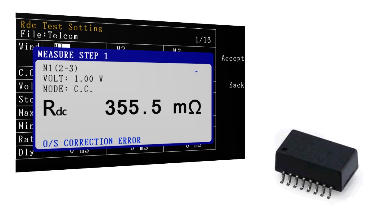
自動平衡ブリッジ測定法によって、4線式測定でDCR(直流抵抗)を測定します。
トランス巻線の各相のDCR値を確認し、トランスの導通回路に接触不良/はんだ付け不良がある可能性があります。
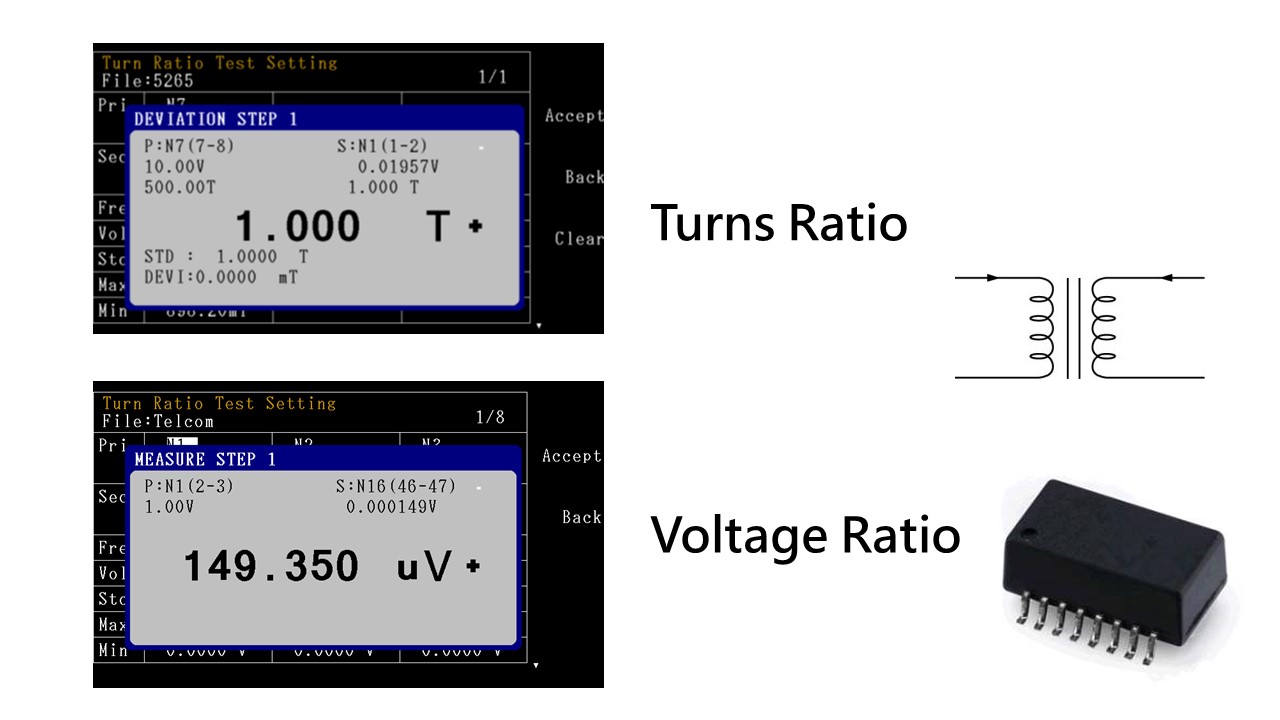
TRUN巻線比
TR巻線比の電圧法とTRL巻線比のインダクタンス法の測定方法を提供できます。
TR方法は一次コイルに交流電圧を加え、二次コイルの交流電圧を測定することです。目的はコイル間の正しい巻数比と位相を測定することです。この方法の利点は測定結果に損失ターン比が含まれることです。この損失ターン比は物理的なターン比よりも大きくなりますが、研究開発エンジニアが得たい電圧値を反映することができます。
TRL方法は各コイルのインダクタンスを測定し、そのインダクタンスを用いてコイル比を計算します。 漏れインダクタンスが大きいトランスでは測定したコイル比の精度がいいです。
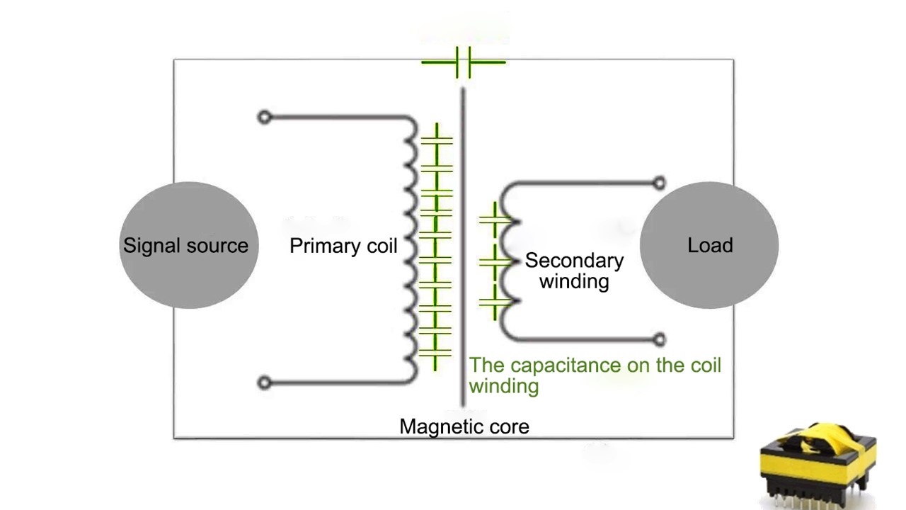
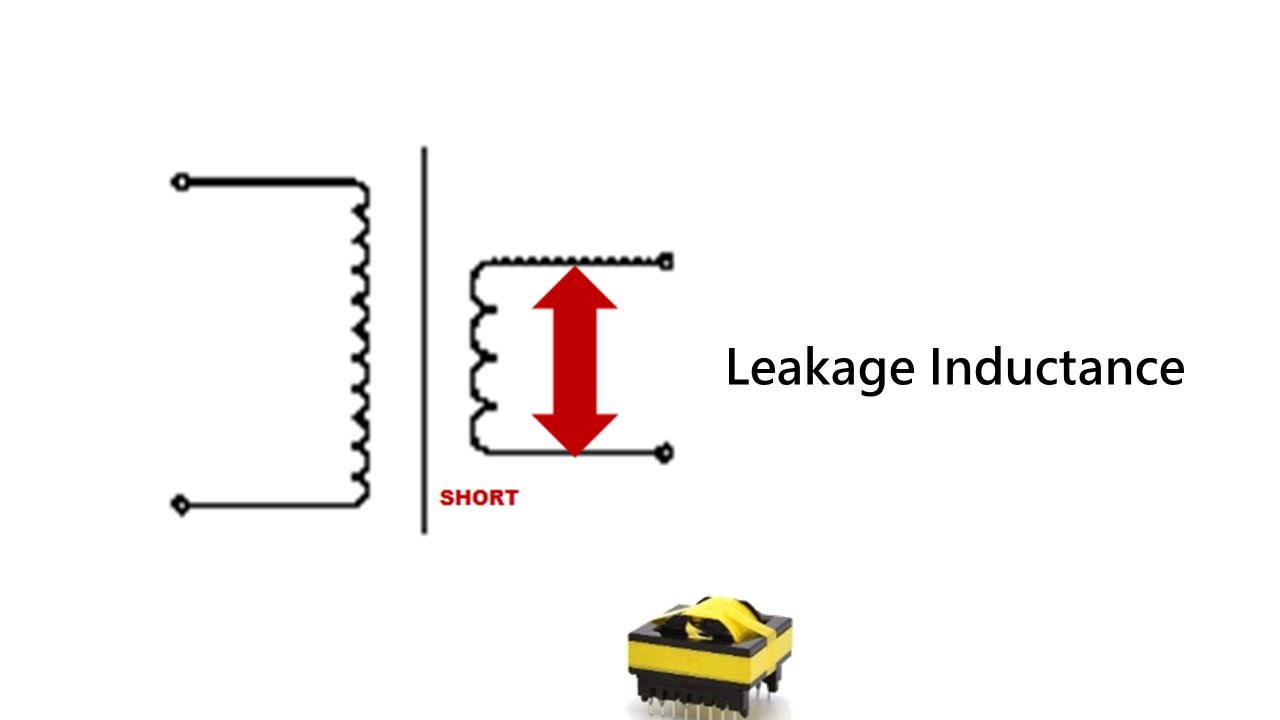
トランスの巻線から発生した寄生容量とリーケージインダクタンスの重要な関係はなんですか。
設計者はトランスの結合係数がk = 1 であることを期待しますが,実際にはトランスのPrimary coilとSecondary coilの結合係数は通常 1 よりも小さくなっています。
コイルによって生成された磁力線はSecondary coilを通過できないため、露出した磁場のインダクタンスが生成されます。Primary coil(Secondary coil)磁束のほとんどは、鉄心を介してSecondary coil(Primary coil)に結合されませんが、空気を介して閉じて、Primary coil(Secondary coil)に戻ります。これは漏れ磁束(LeakageInductance)と呼ばれます。このようなコアギャップによる漏れ磁束は、高周波状態で使用されるフェライトコア材料の透磁率を低下させ、トランスの性能を低下させます。
リーケージインダクタンス(Lk)の低減方法は何ですか。
一般にトランスの漏れインダクタンスはPrimary coilの巻数の2乗に比例するので、巻数を減らすことで漏れインダクタンスを低減したり、Primary coilを内層と外層に置き、中間でコイルを挟む(サンドイッチのように巻きます。)ことも可能です。Primary coilの層数が多すぎると,リーケージインダクタンスが大きくなり,寄生容量の分布も大きくなるため,高周波での結合度が高くなり,スイッチに過渡振動が発生してトランスやスイッチングデバイスの損失が大きくなることがあります。
LCR平衡ブリッジ法によるトランスの漏れインダクタンスの測定は、トランスの1次コイルに測定器を接続し、2次コイルをオープンにしたとき、測定器で測定したインダクタンスL=1次コイルのインダクタンスLp+漏れインダクタンスLKとします。 (理想的な2次コイルが短絡すると、2次コイルの電圧は0Vとなり、1次コイルの両端の0V状態がトランスに反映されます)。
安全認証試験項目
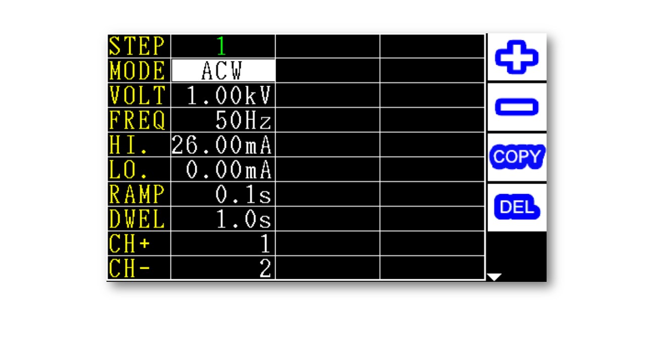
交流耐電圧試験
直流耐電圧試験
絶縁抵抗試験
漏れ電流試験
AC耐電圧試験とDC耐電圧試験をしたの長所と短所は何ですか?
ほとんどの被測定物にはAC電圧試験では満たされないような小さな浮遊容量が含まれており、その浮遊容量に連続した電流が流れます。
長所
短所
DC耐圧試験を使用すると、対象物にそれ自体の小さな浮遊容量が充填されるため、浮遊容量が充填されると直流電圧試験による静電容量電流はゼロに近くなります。
長所
短所
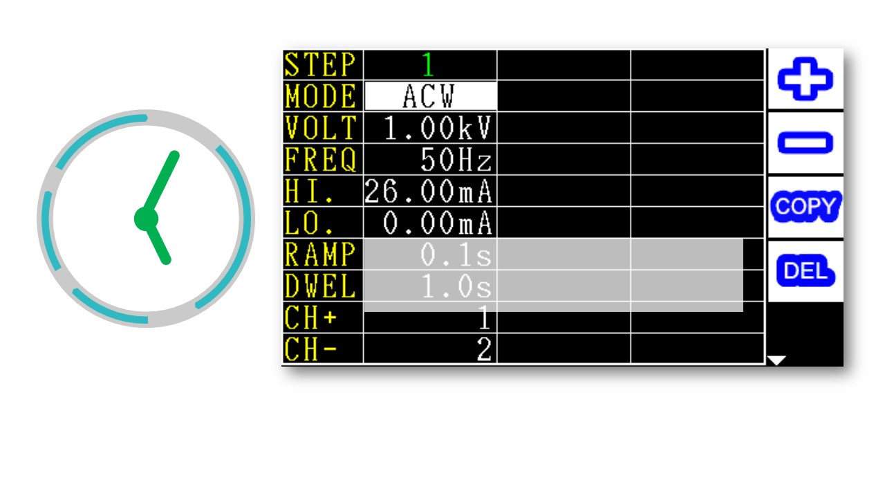
耐圧試験の時間はどのくらいに設定すればよいのでしょうか?
業界で最も一般的な生産ラインのテストは耐圧試験です。
ほとんどの製品は連続加圧試験時間が60秒となっていますが、試験対象物が数グループある場合は、1つのDUTを完成させるのに60秒の数倍の時間がかかり、非常に時間のかかる加圧試験となっています。実際に生産ラインで行われているのは電圧試験の時間を1~2秒に短縮し、試験電圧を10~20%上げることで、時間短縮後の製品の絶縁性能の信頼性を確保する方法が一般的です。
絶縁インピーダンス試験が必要な理由は何ですか。
アーク検知により、製品が放電不良か確認できます。
漏れ電流試験
変圧器は高電圧や高電流にさらされることで、絶縁被覆を貫通する部分放電が発生する可能性があります。
短時間の耐電圧試験では変圧器の実際の寿命を正確に評価できないため、インパルス試験が必要とされています。
標準付属品
| Power Cord | |
| フィクスチャー (F7721) | 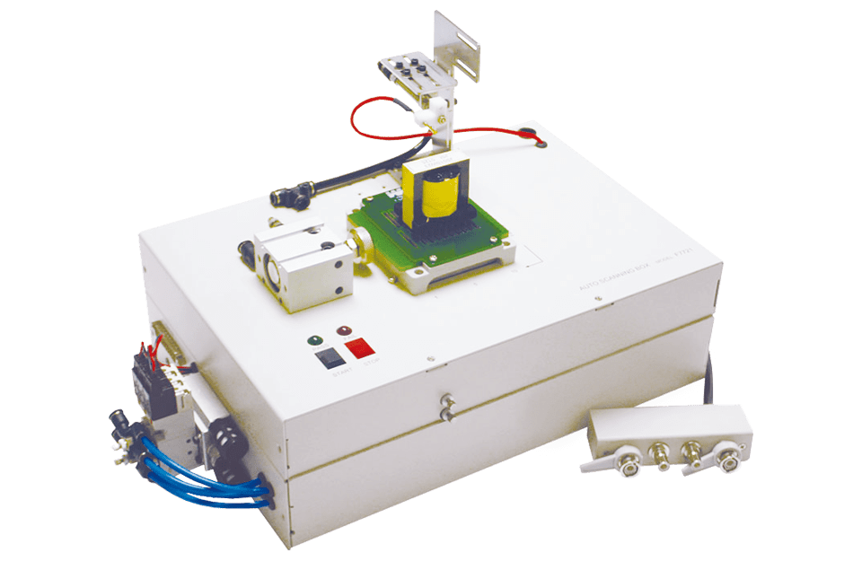 |
| フットスイッチ (F522010) | |
| 高圧テストリード | |
| 25Pin-25Pin ケーブル | |
| 24Vスイッチパワーサプライ | |
オプション付属品
| PC Linkソフトウェア | |
| ケーブル (RS-232) | |
| フィクスチャー (F7721-D) | 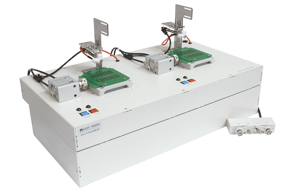 |

