Stator Coil/Core
The purpose of stator core is to be part of the magnetic route and the place to fix the stator coil. This core is made of couple 0.5mm silicon steel sheets. To lower the magnetic loss, the core will cover by insulating paint to isolate each piece. There are couple sockets in the core to fix the stator coil.
Stator coil is an important component of motor. The purpose is to create inductance by current. There are single layer and double layers on the iron core.
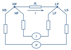
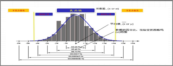
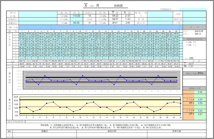
Uneven DCR happen in 3-pase motor, this will cause uneven rotate.
MICROTEST 4-Wire DC Resistance measurement will be more accurate than others.
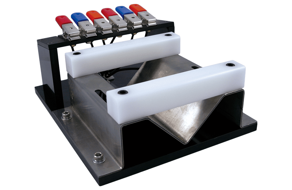
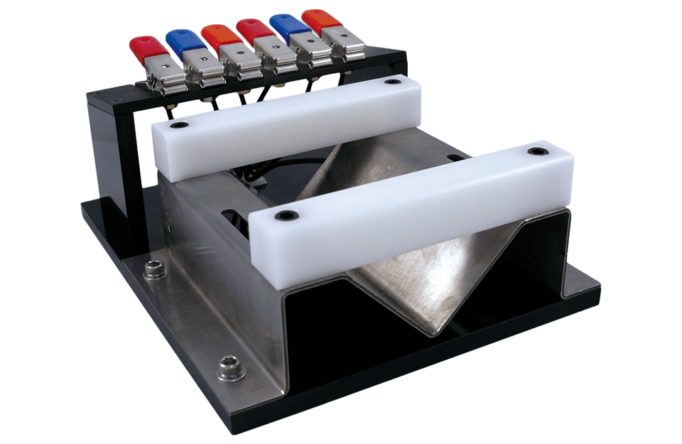
Customized test fixture for stator coil
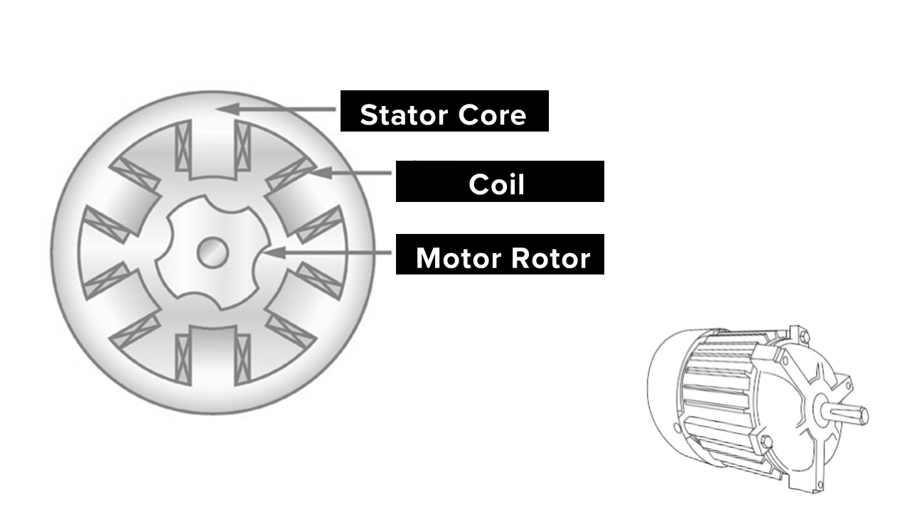
For Enameled Winding of Motor
- Conduct coil’s quality issue.
- Layer Short Between Winding
- Short on cross winding
- Pin Short
- Insulation Defect
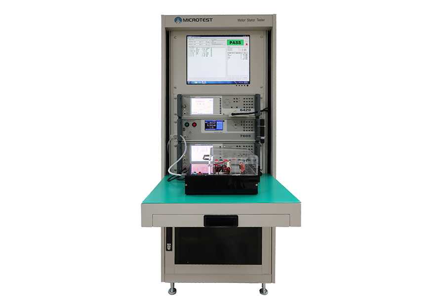
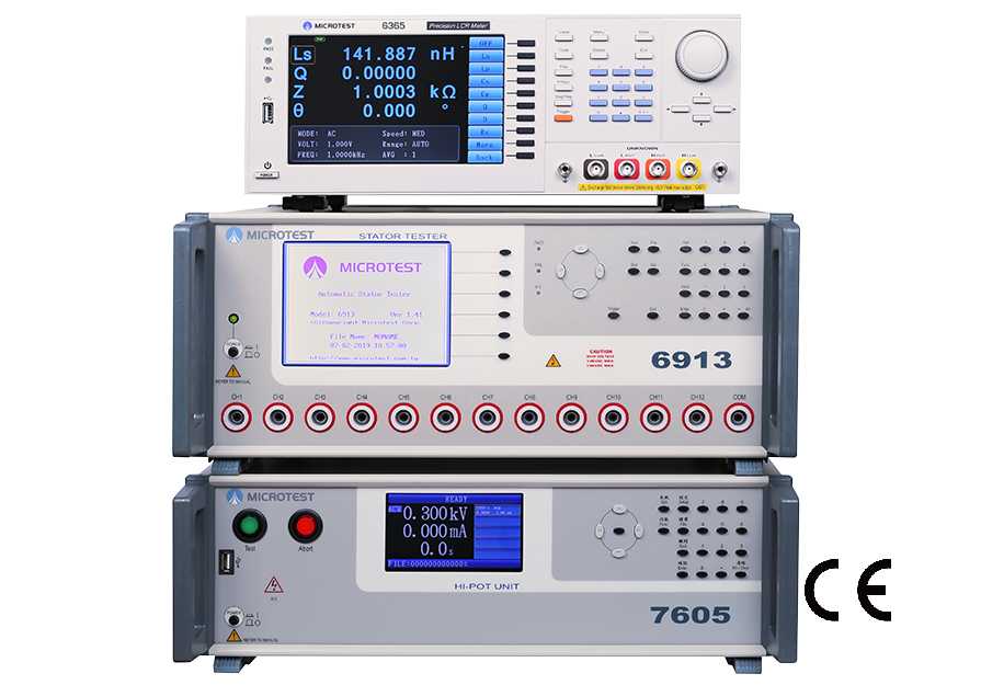
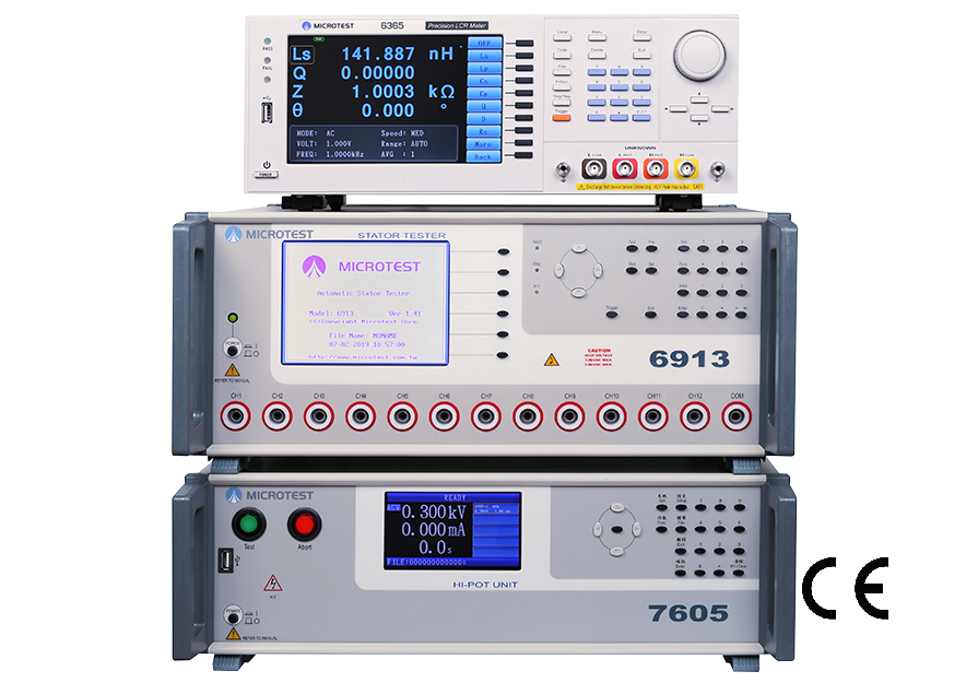
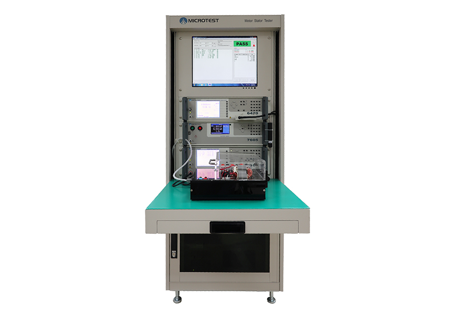
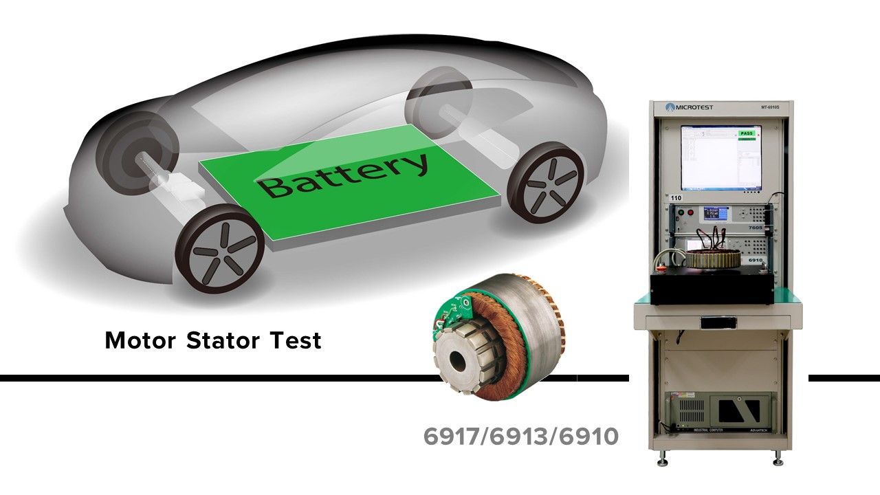
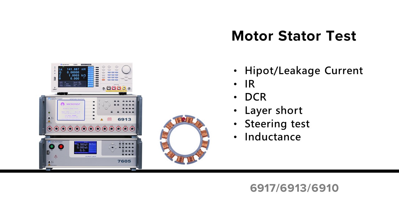
MICROTEST Motor Stator Testing System is One-Step-Test Function
Low Voltage Electrical Test + Hipot Test + Layer Short
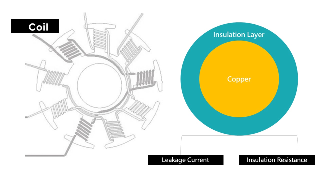
Important Parameter for Quality of Coil
- Regular motor is winding on Silicon steel sheet
- Prevent the electricity from enameled wire to motor
- Put a insulation material on silicon steel sheet
- Insulation paint on enameled wire
- Short might happened while the current is passing the defect winging coil.
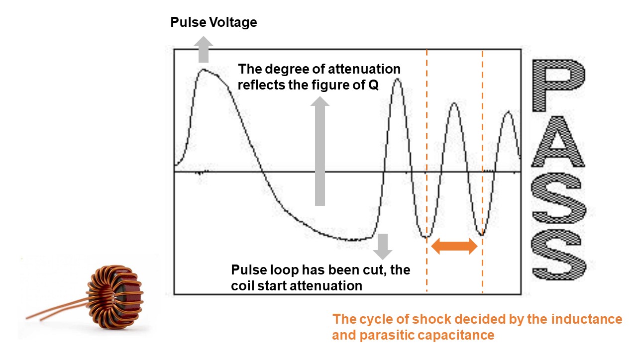
Introduction of Impulse Tester
Impulse Winding Tester use the comparison of pulse to measure the DUT. The instrument provide high voltage to do the instant pulse test and record the wave. Compare with the golden sample to define the product.
Why do we need impulse tester for producing motor/transformer?
Impulse Test = Quality and product life test
The small defection is hard to find at low voltage test station. As the DUT goes to the final assembly test, the defect may show up. This will higher the cost of production.
Motor and transformer usually work under high voltage. If we add impulse test in the product line, this may prevent the malfunction or burn on motor.
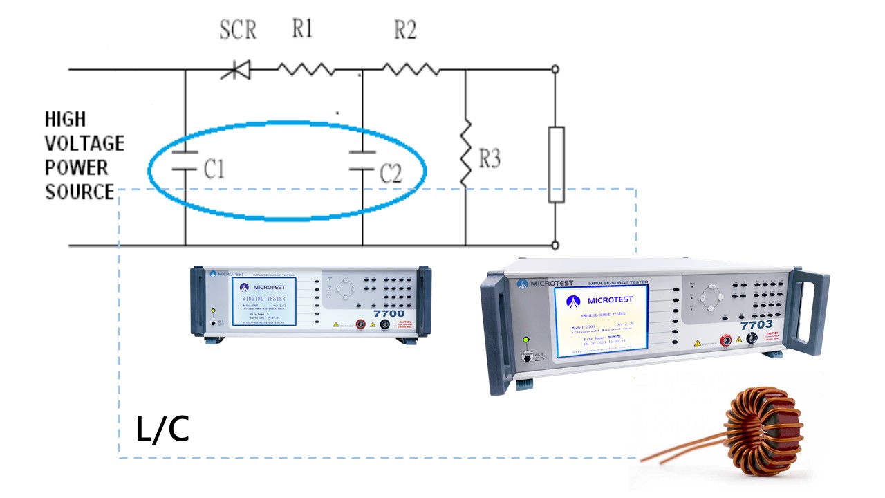
| L |
is the DUT coil |
| C1, C2 |
are the resonant capacitors in the instrument |
| R1, R2, R3 |
is the resistant in the instrument and the DUT |
| Technology of Detect Layer Short |
| → 1 |
Charge the C1 capacitor to the certain testing voltage level. |
| → 2 |
Trigger the SCR by pulse |
| → 3 |
DUT will resonate with C1 and C2 |
Technology of Detect Layer Shor
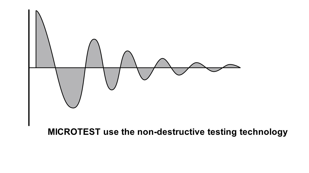
“Pulse voltage and waveform comparison” is the way we detect layer short. The pulse voltage is non-destructive/instant voltage that apply on both side of winding and detect the DUT without damage it. By compare the wave with the golden sample, we can judge the DUT.
Damping wave under L/C resonate comes from the feature change of defect coil.
- Inductance of coil
- Q rate
- Turn ratio of coil(voltage different)
- Material of core
- Layer short in the coil
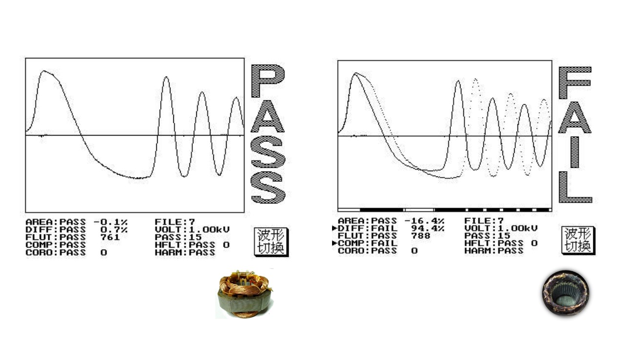
By comparing the wave of damping attenuation between golden sample and DUT
Provides 5 waveform comparison
- Total area comparison
- Differential area comparison
- Wave comparison
- Flat comparison
- Corona comparison


