14F-6, No. 79, Sec. 1, Xintai 5th Rd, Xizhi Dist., New Taipei City, 221432 Taiwan (R.O.C.)
Tel: 886-2-2698-3877
Fax: 886-2-2698-4089
email : [email protected]

When conducting high-capacitance MLCC capacitance measurements, it is common to encounter situations where the measured values do not match the nominal capacitance specified in the product datasheet.
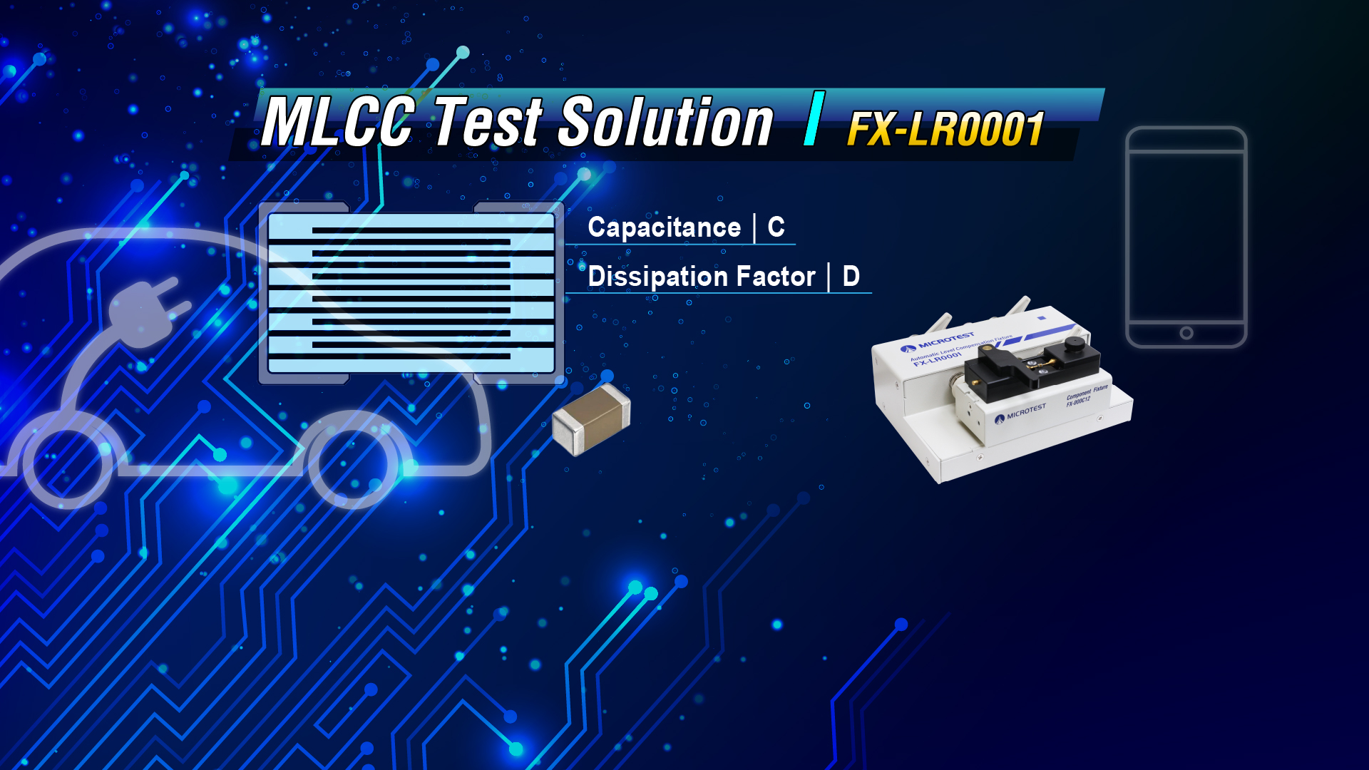
Here are the correct measured capacitance values (C) and dissipation factors (D) provided
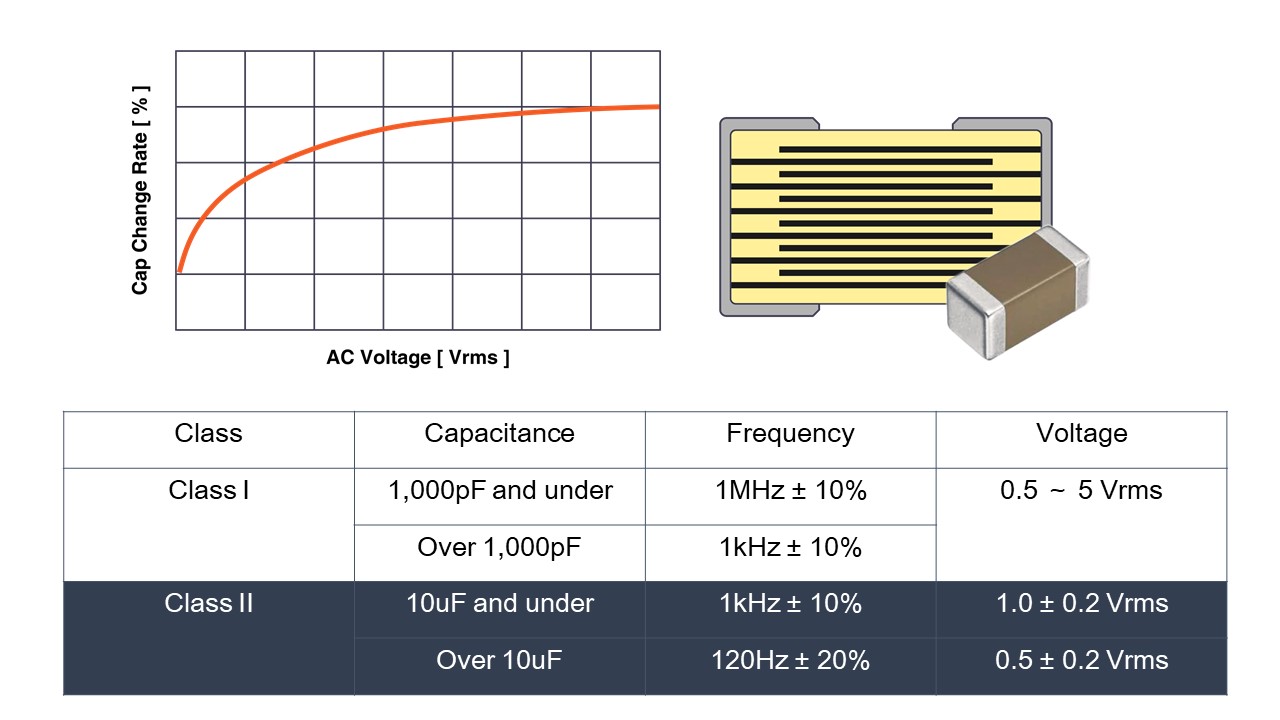
Due to the use of high dielectric constant insulating materials in MLCCs, they exhibit non-linear behavior in the low voltage range. This non-linearity causes the measured capacitance to vary with different applied voltages. The regulation (JIS C 5101-1-1998) specifies standards for the test signal.
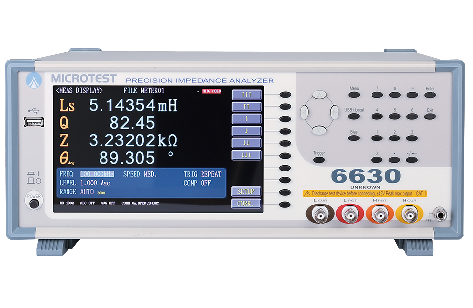
For measuring MLCC capacitance, we typically use an LCR meter. However, LCR meters often experience voltage division due to the influence of current-limiting resistors when generating the output voltage signal. This can result in discrepancies between the measured values and the nominal capacitance stated in the product specification.
The circuit added in the test circuitry to stabilize the voltage level automatically corrects the offset voltage back to the user-set voltage signal value, enabling precise measurement of MLCC (Class 2) components of this kind.
|
|
|
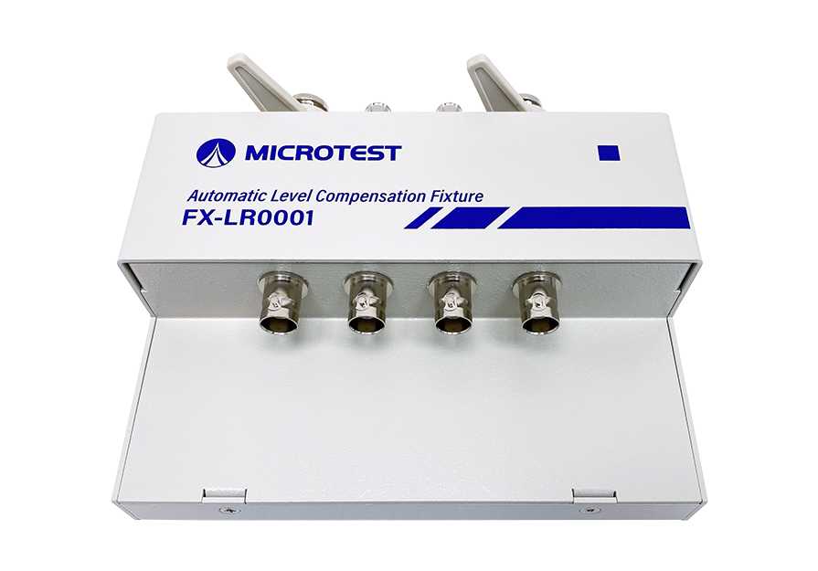
| Option Automatic Level Compensation Fixture (FX-LR0001) | 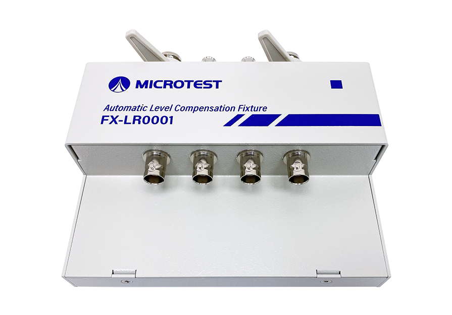 |
|
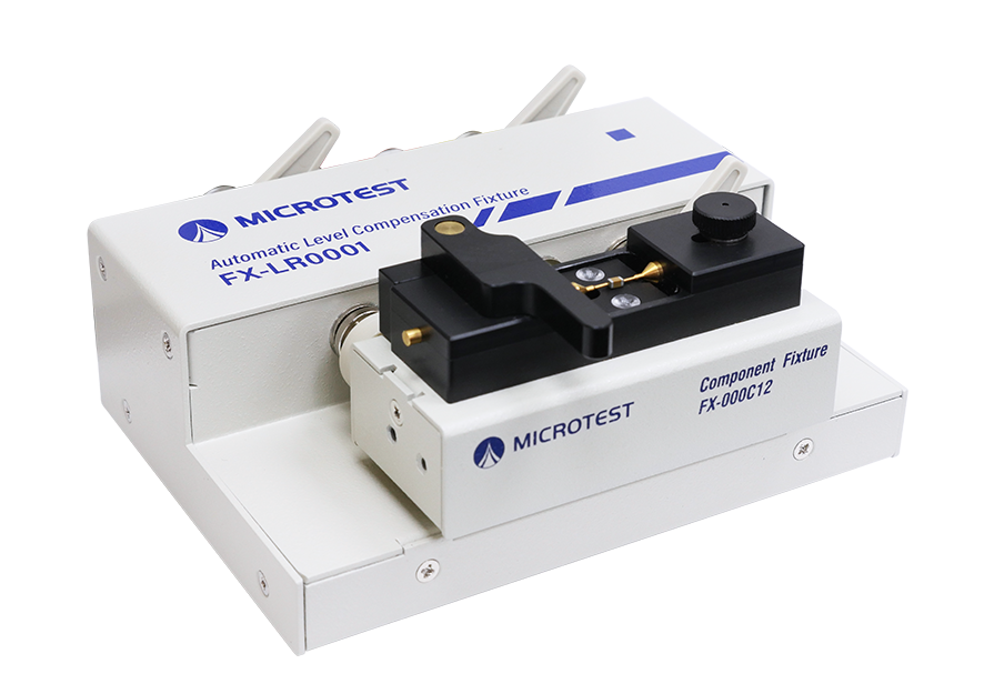
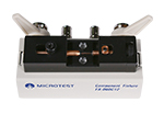
Option SMD component testing fixture (FX-000C12) |
 |
Taking a practical example of a 10uF MLCC (Class 2) component
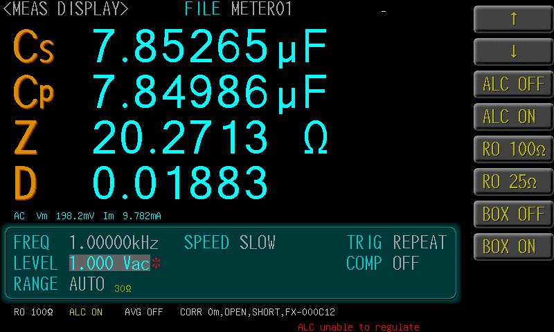
The measured capacitance value of 7.8uF (lower than the standard value) when AC level mode is not supported.
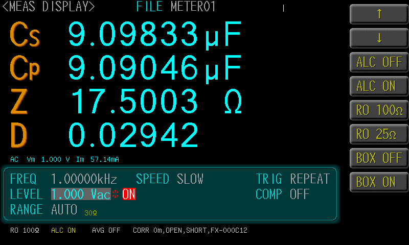
Use of FX-LR0001, which supports AC level compensation.
After applying AC level compensation, the measured capacitance value is closer to the standard value of 10uF.