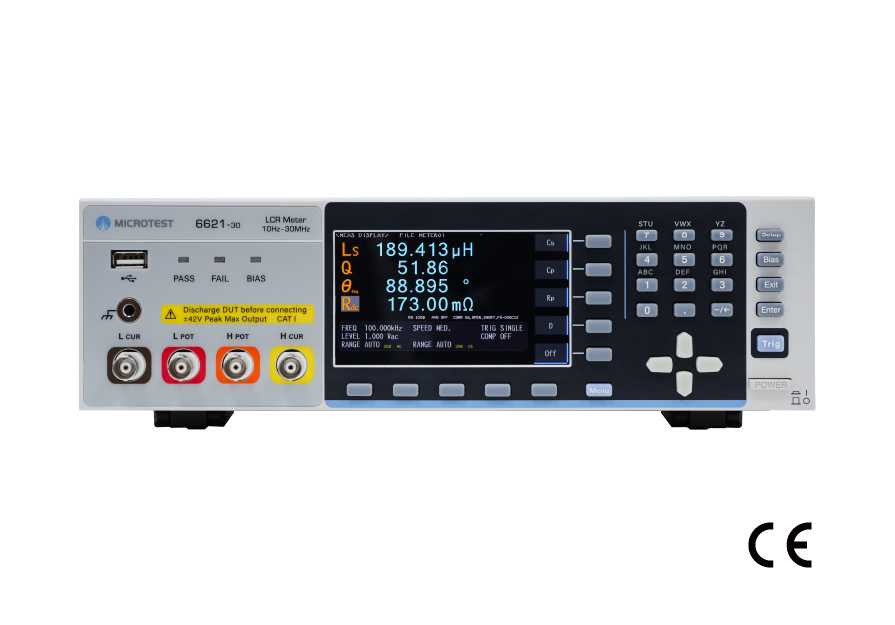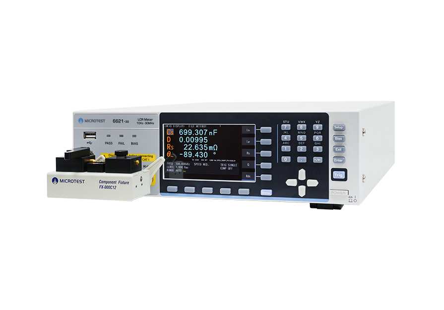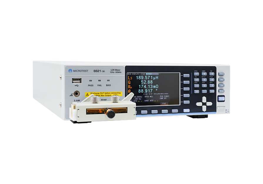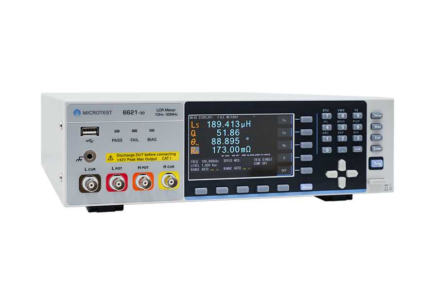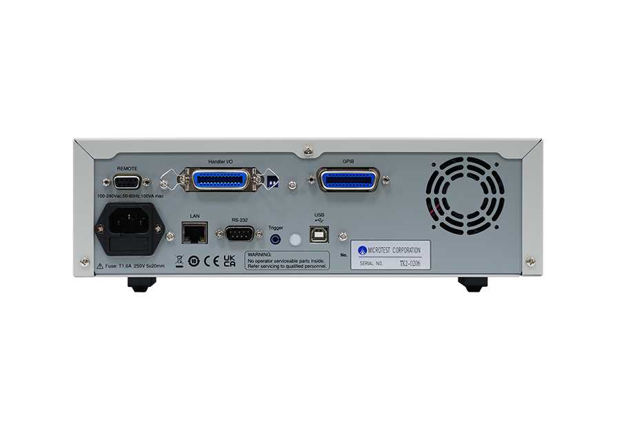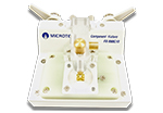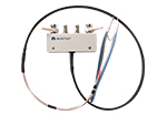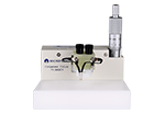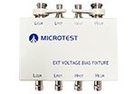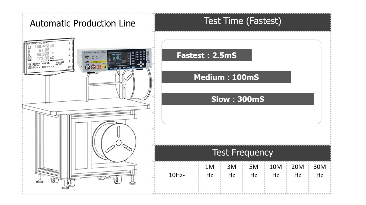
MICROTEST 6621 LCR Meter provides a wide frequency range of10Hz to 30MHz for measuring the impedance characteristics ofcomponents and materials. The measured parameters include |Z| , |Y| , θ , X ,R , G , B ,L , D , Q , DCR , C. It supports REMOTE/Handler/LAN/USB Host/USB Device/RS-232/GPIB(Optional)communication interfaces, making it compatible with automation equipment or human-machine interfaces (PLC).
Selection
| 6621 Series | ||||||
| Model | 6621-1 | 6621-3 | 6621-5 | 6621-10 | 6621-20 | 6621-30 |
| Frequency |
10Hz- 1MHz |
10Hz- 3MHz |
10Hz- 5MHz |
10Hz- 10MHz |
10Hz- 20MHz |
10Hz- 30MHz |
SPEC
| Model | 6621 | |
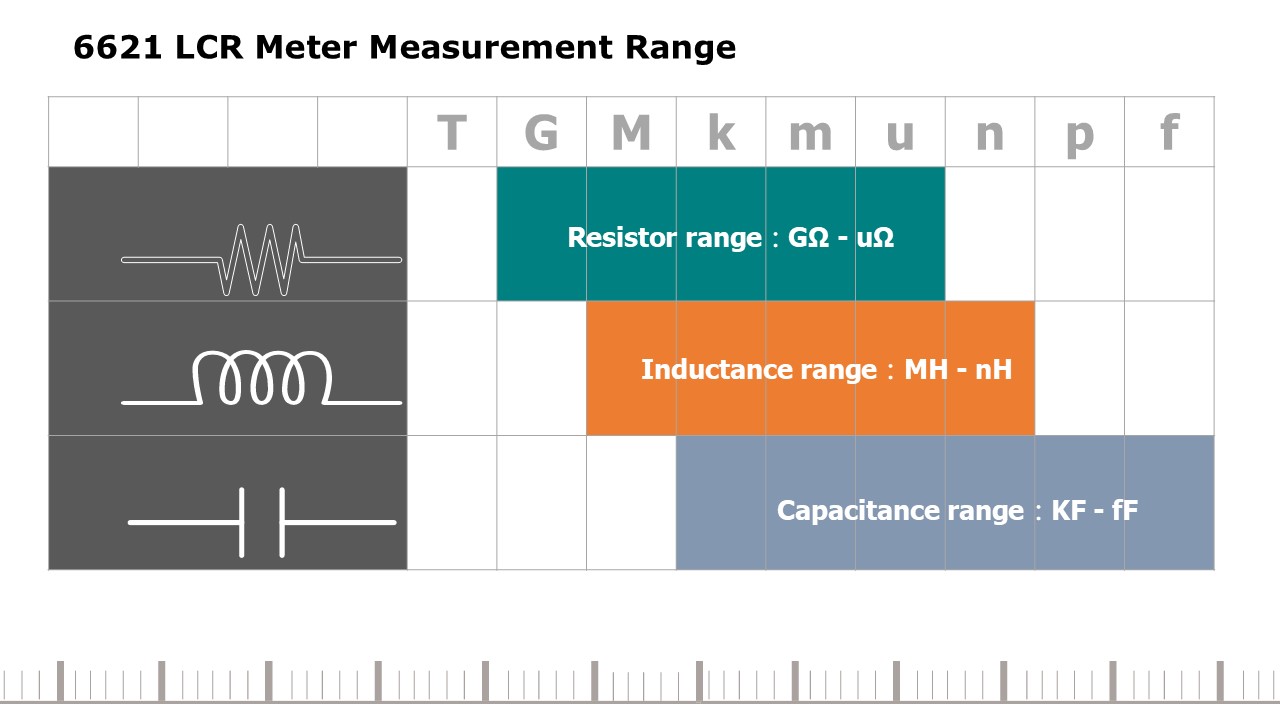
| Frequency Range | 10Hz-30MHz | |
| Frequency Setting | Continuity | |
| Frequency Resolution | ±0.01% | |
| Frequency Output Accuracy | 100mHz, 6-bit Frequency Input | |
| Basic Accuracy | typical ±0.05% | |
| AC Drive Level | Test Signal Voltage Level |
10mV - 2Vrms(100Ω) 10mV - 1Vrms(25Ω) |
| Voltage Minimum Resolution | 1mV | |
| Accuracy |
ALC ON:6% * Voltage ±2mV ALC OFF:10% * Voltage ±2mV |
|
| Test Signal Current Level | 200µA - 20mArms | |
| Current Minimum Resolution | 10µA | |
| Accuracy |
ALC ON:6% * Current ± 20µA ALC OFF:10% * Current ± 20µA |
|
| DC Drive Level | 1V (fixed) | |
| Output Impedance | 25Ω/100Ω (switchable) | |
| Measurement Mode | Meter mode, list mode | |
| Measurement Parameters |
|Z|、|Y|、θ、X、R、G、B、L、D、Q、DCR、C |
|
| Test Time (Fastest) | < 3mS | |
Measurement Parameters
| Parameters | Range |
| |Z| | 0.000 mΩ to 9999.99 MΩ |
| R, X | ± 0.000 mΩ to 9999.99 MΩ |
| |Y| | 0.00000 μS to 999.999 kS |
| G, B | ± 0.00000 μS to 999.999 kS |
| θRAD | ± 0.00000 to 3.14159 |
| θDEG | ± 0.000° to 180.000° |
| Cs, Cp | ± 0.00000 pF to 9999.99 F |
| Ls, Lp | ± 0.00 nH to 9999.99 kH |
| D | 0.00000 to 9999.99 |
| Q | 0.00 to 9999.99 |
| Δ | ± 0.00% to 9999.99% |
| Rdc | 0.00 mΩ to 99.9999 MΩ |
System
| Measurement Circuit | Series/Parallel |
| Correction | Open Circuit/Short Circuit/Load correction |
| Cable Compensation | 0 / 0.5 / 1 /2 (m) |
| BIN | ABS、ΔABS、Δ%、OFF |
| Comparator | 9 |
| List Mode | 50 groups of Multi-steps setting (Each group contains up to 15 steps) |
| Bulit-in Storge | 100 sets LCR setting documents, 50 groups of list mode setting |
| USB Host Storge | LCR setting documents, list mode setting document, BMP graphics, Sweep screen and test result data |
| Trigger Test | Auto, manual, RS-232, Handler |
| Power Supply | Voltage:90-264Vac |
| Frequency:47-63Hz | |
| Power consumption | 30VA |
| Environment | Temperature:10℃-40℃ |
| Humidity:20-90%RH | |
| Dimension | 300x89.1x362.8 mm (W*H*D) |
| Weight | 3.4 Kg |
| Interface | RS-232、Handler、LAN、USB Host、USB Device |
| Display | 4.3"TFT,color screen (800*480) |
The Ideal LCR Meter for Component Sorting Systems
6621 LCR Meter is capable of displaying up to four measurement parameters simultaneously. It supports concurrent AC and DC measurements.
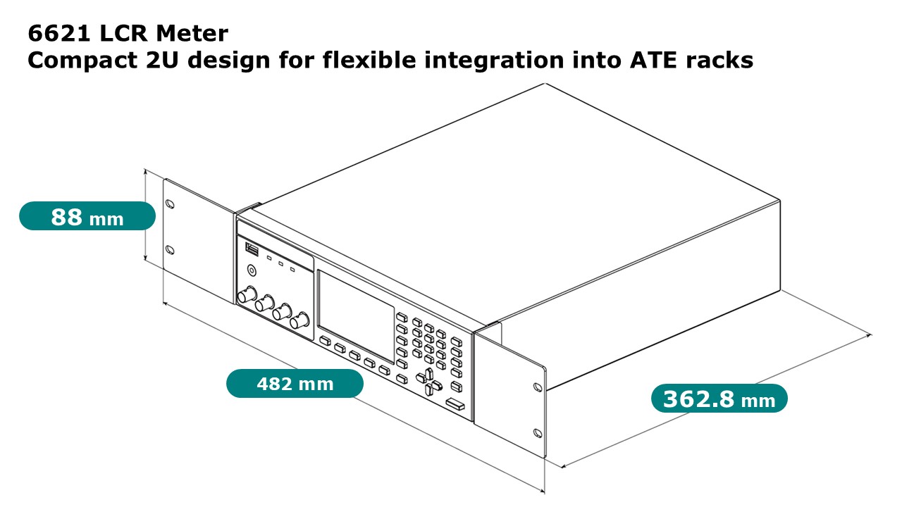
6621 Compact Design – 2U Height for Flexible ATE Integration
The 6621 LCR Meter features a compact form factor with a 2U height, allowing easy integration into automated test equipment (ATE) rack systems and significantly saving system space.
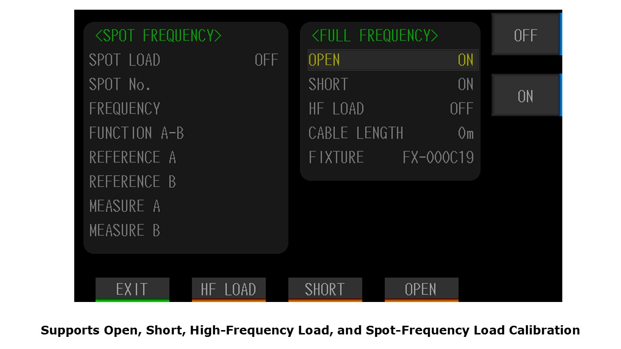
Supports Open, Short, High-Frequency Load, and Spot-Frequency Load Calibration
Before measurement, perform open, short, high-frequency load, and spot-frequency load calibration to eliminate errors caused by test leads and measurement circuitry.
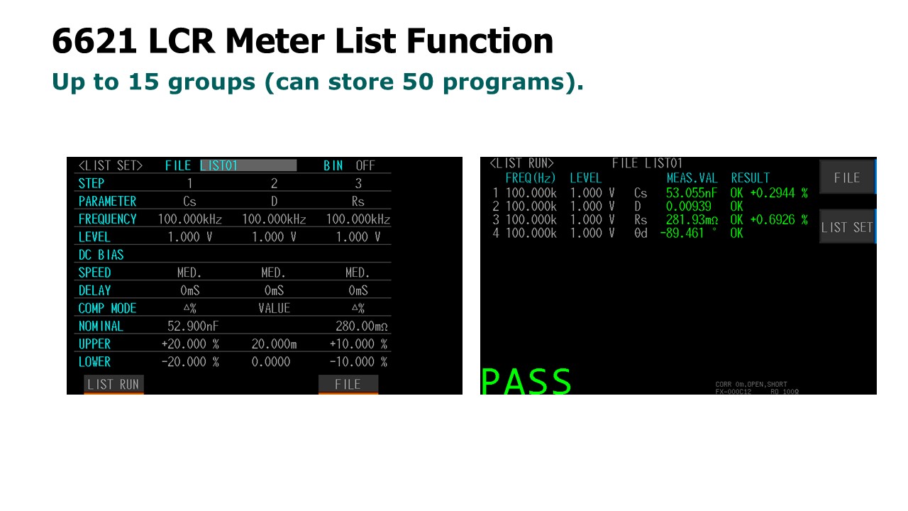
6621 Support The List Mode
50 groups of list mode setting (Each group contains up to 15 steps).
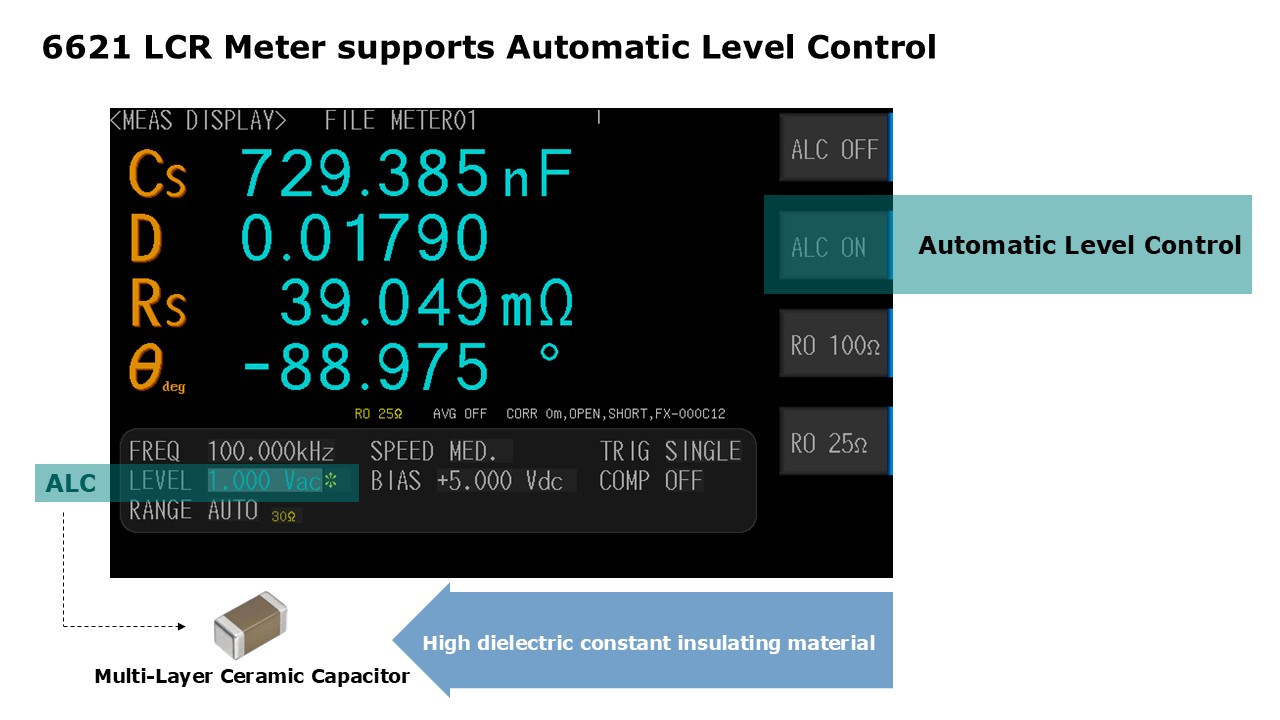
Precision Calibration, Automatic Level Control (ALC), Selectable Output Impedance (25 Ω / 100 Ω)
Utilizes automatic balancing bridge measurement technology, supporting both 25Ω and 100Ω output impedance modes to meet users'
requirements for compatibility with other instruments.
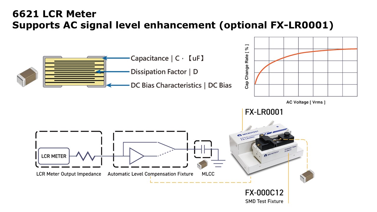
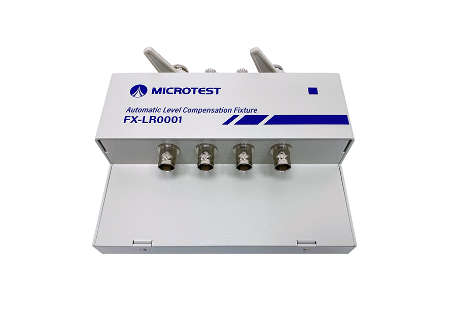
6621 supports AC signal level enhancement (optional FX-LR0001)
According to the JIS C 5101-1-1998 standard, AC test signal levels must be properly regulated when measuring MLCC capacitance. LCR meters should enable Automatic Level Control (ALC) to maintain a stable signal level and correct any deviation to match the user-defined voltage.
For enhanced accuracy, the optional external AC level compensation box (FX-LR0001) can be used to ensure stable output that accurately reflects the DUT characteristics.
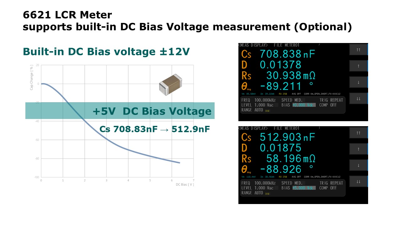
Supports Built-in DC Bias Measurement (Optional OP-662102)
In electronic circuit design, capacitors are essential for filtering, decoupling, energy storage, and voltage regulation. However, their actual performance is affected by capacitance drop under DC bias. When a DC voltage is applied, the internal electric field suppresses dielectric polarization—particularly in high-k ceramic materials—leading to a significant reduction in capacitance.
If this effect is overlooked in power modules, decoupling, DC-DC converters, or high-speed communication systems, it may result in poor ripple suppression, instability, or degraded EMI performance.
The optional OP-662102 module provides a built-in ±12 V DC bias function for evaluating MLCCs under DC bias, ensuring sufficient capacitance for reliable system operation.
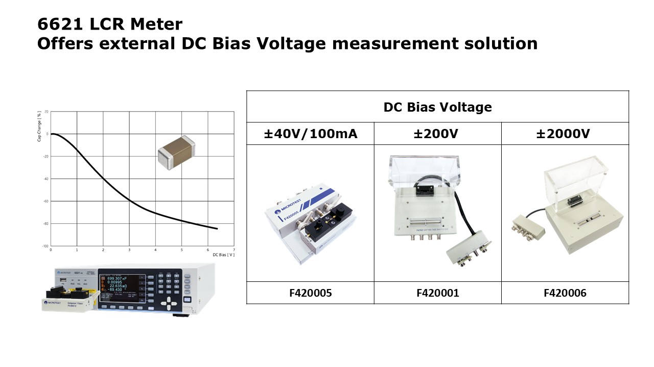
An external DC bias measurement solution is also available, supporting bias voltages of ±40 V, ±200 V, and ±2000 V via optional external DC bias boxes.
Inductor manufacturers typically define the saturation current as the current value at which the inductance decreases by a specified percentage (e.g., 10% or 30%). This is because when a DC bias current is applied, the magnetic core begins to saturate, reducing its ability to store magnetic energy. As a result, the inductance drops significantly.
Measuring inductance under DC bias conditions is essential for accurately evaluating inductor performance in real-world applications such as power converters, where steady DC currents are present.
Inductor Saturation Current Measurement Solution- 6621+ Series
6621 LCR Meter can be equipped with a DC bias current source to measure the inductor's saturation current characteristics. The maximum
output current for superimposed bias is 640A, with a frequency response range of 100Hz to 10MHz. This setup allows for the verification and
testing of the change in inductance value when a DC bias current is applied to the inductor.
6621+ Series (LCR Meter with DC Bias Current Source)
Ordering Information
| LCR Meter | 6621-1 (Test Frequency 10Hz-1MHz) | |
| 6621-3 (Test Frequency 10Hz-3MHz) | ||
| 6621-5 (Test Frequency 10Hz-5MHz) | ||
| 6621-10 (Test Frequency 10Hz-10MHz) | ||
| 6621-20 (Test Frequency 10Hz-20MHz) | ||
| 6621-30 (Test Frequency 10Hz-30MHz) | ||
| Standard | ||
| Power cord | ||
| 選購配件 | ||
![]() |
F423906A/B |
Kelvin Clip Leads (100cm) Kelvin Clip Leads (50cm)
|
![]() |
FX-000C12 | SMD Test Fixture |
![]() |
FX-000C10 | Bottom Electrode SMD Test Fixture |
![]() |
FX-000C11 | SMD Tweezers Test Leads |
![]() |
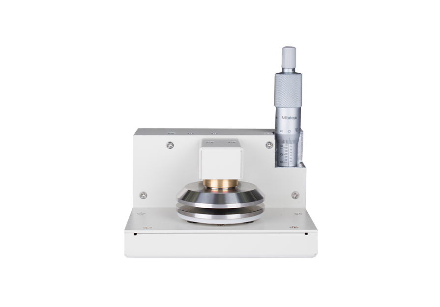
FX-0000C9 | Material Testing Fixture |
![]() |
F420003 | External Voltage Bias (±40V/1MHz) |
![]() |
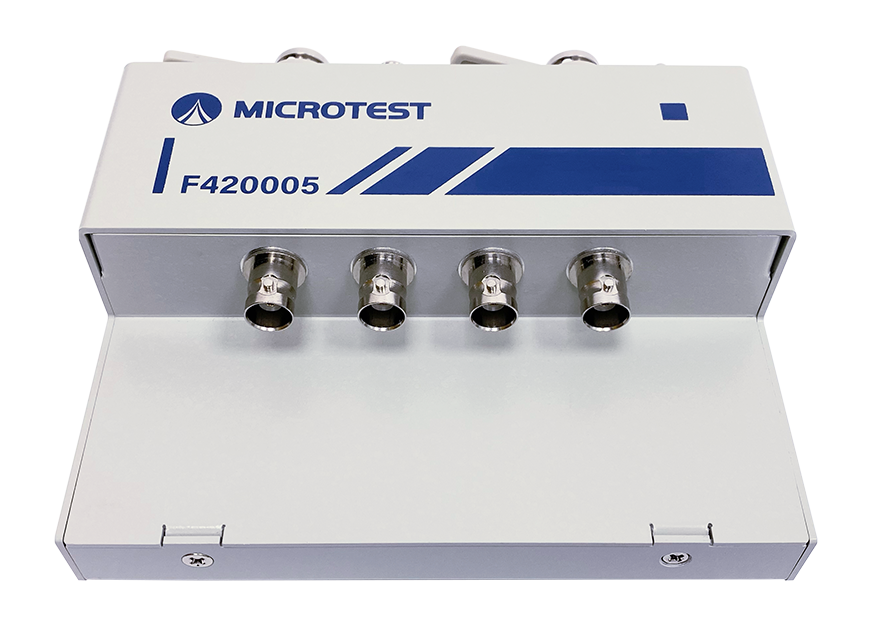
F420005 | External Voltage/ Current Bias (±40V/100mA) |
![]() |
F420001 | External Voltage Bias (±200V/1MHz) |
![]() |
F420006 | External Voltage Bias (±2000V/1MHz) |
![]() |
F663001 A/B/C | F663001A BNC Test Leads (50cm) F663001B BNC Test Leads (100cm) F663001C BNC Test Leads (200cm) |
![]() |
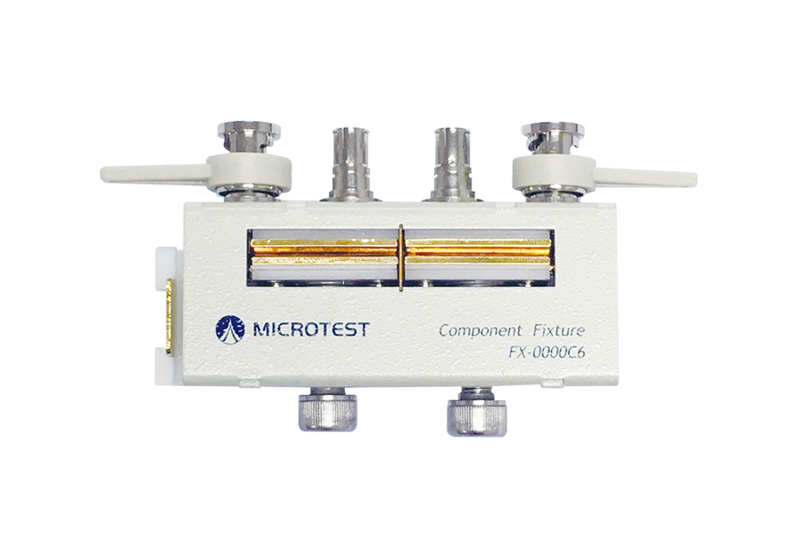
FX-0000C6 | DIP Test Fixture |
![]() |
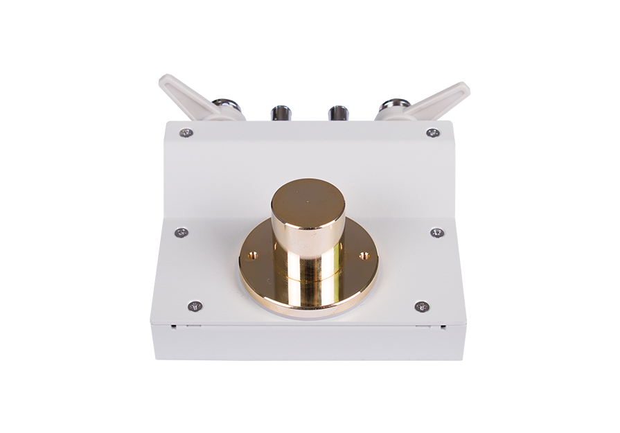
FX-0000C7 | Dielectric Materia |
![]() |
FX-0000C8 | Magnetic Material Test Fixture |
![]() |
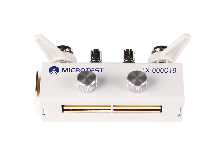
FX-000C19 | DIP Test Fixture |
![]() |
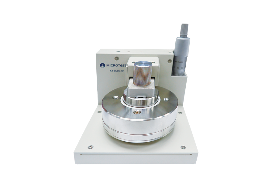
FX-000C20 | Liquid Dielectric Material Test Fixture |
![]() |
FX-LR0001 | Automatic Level Compensation Fixture |
![]() |
FX-0000C4 | DIP Test Fixture |
![]() |
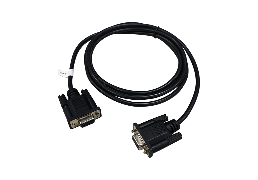
TL-000003 | RS-232 Cable (180cm) |
![]() |
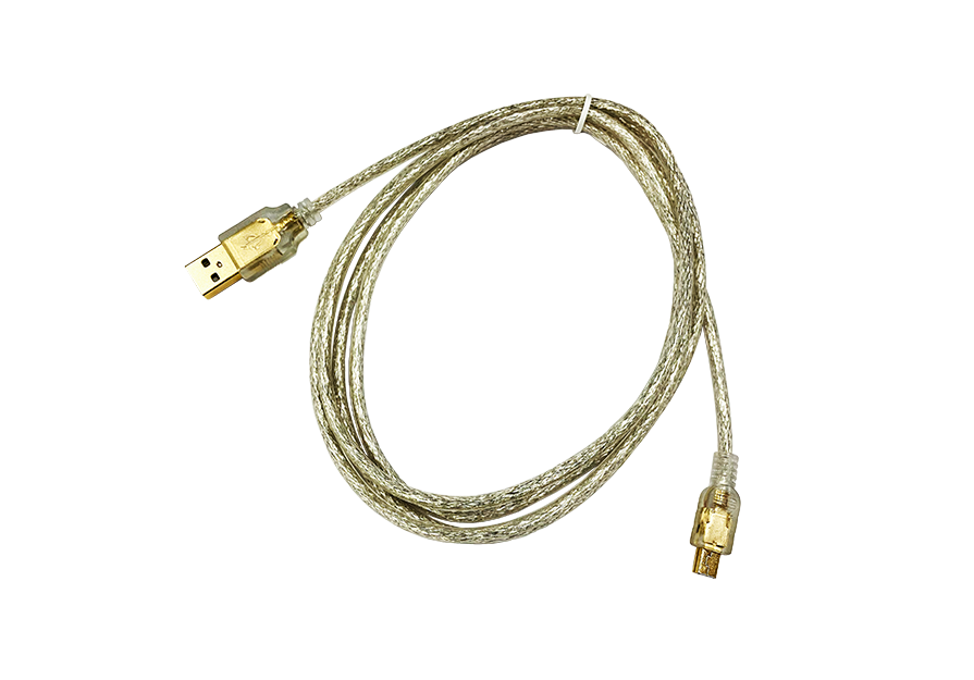
TL-000007 | USB Cable (180cm I Type-A TO Type-B) |
| OP-662101 | GPIB Interface | |
| OP-662102 | Built-in DC Bias Voltage ±12 | |
| 6621+ Series DC Bias Current Test Syste | ||
| PC Link Software | ||