14F-6, No. 79, Sec. 1, Xintai 5th Rd, Xizhi Dist., New Taipei City, 221432 Taiwan (R.O.C.)
Tel: 886-2-2698-3877
Fax: 886-2-2698-4089
email : [email protected]


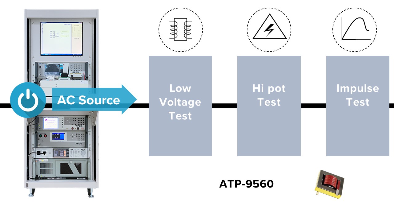
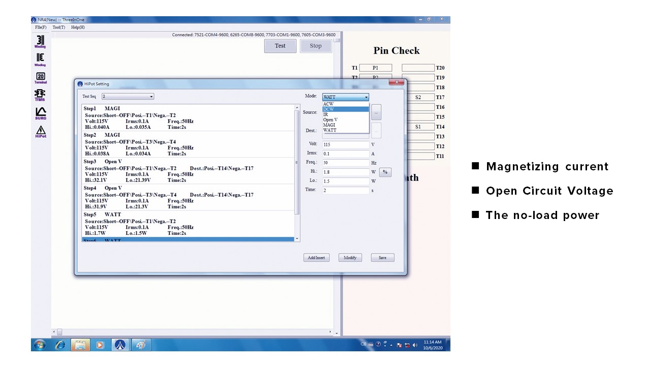
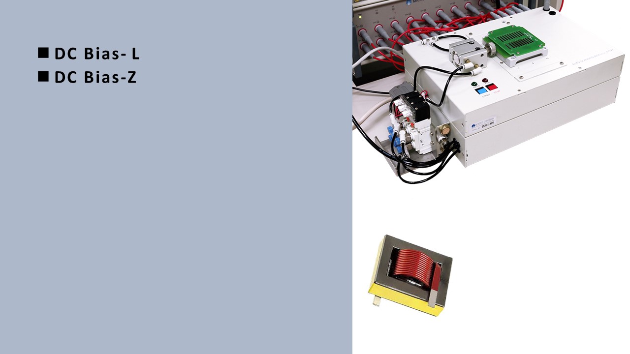
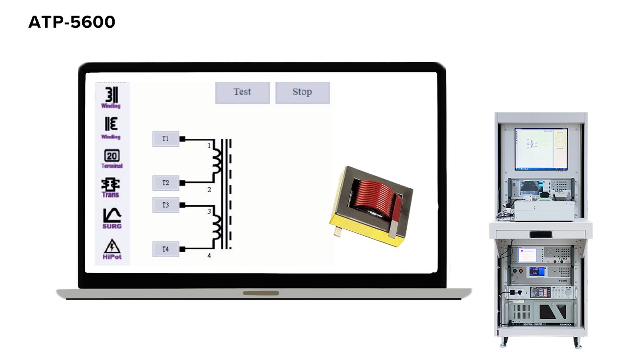
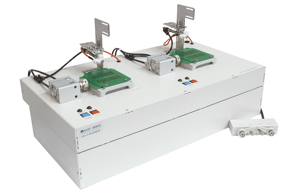
The MICROTEST 9560 Transformer Integrated Test System is a comprehensive measurement system that integrates low-voltage electrical characteristics and safety compliance testing into a single platform. Controlled by a PC, it provides 20 test channels. The system integrates an AC source for dynamic testing of transformers (open-circuit voltage, excitation current, no-load power) and measures the inductance value of transformers. The optional LCR Meter offers test frequencies of 200kHz, 500kHz, and 1MHz.
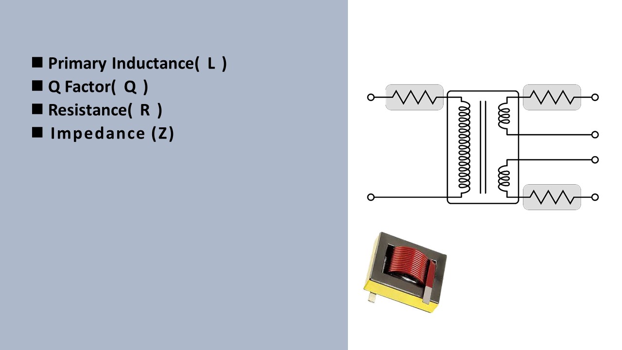
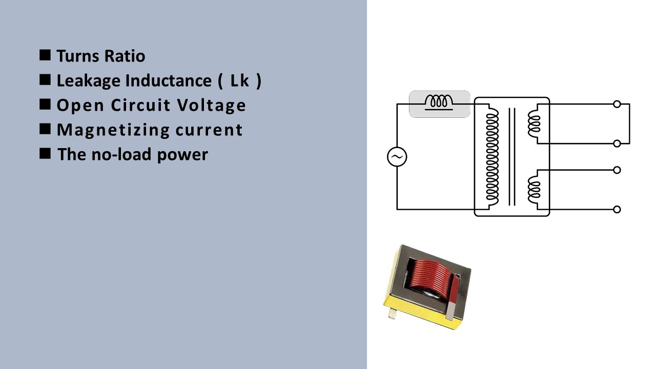
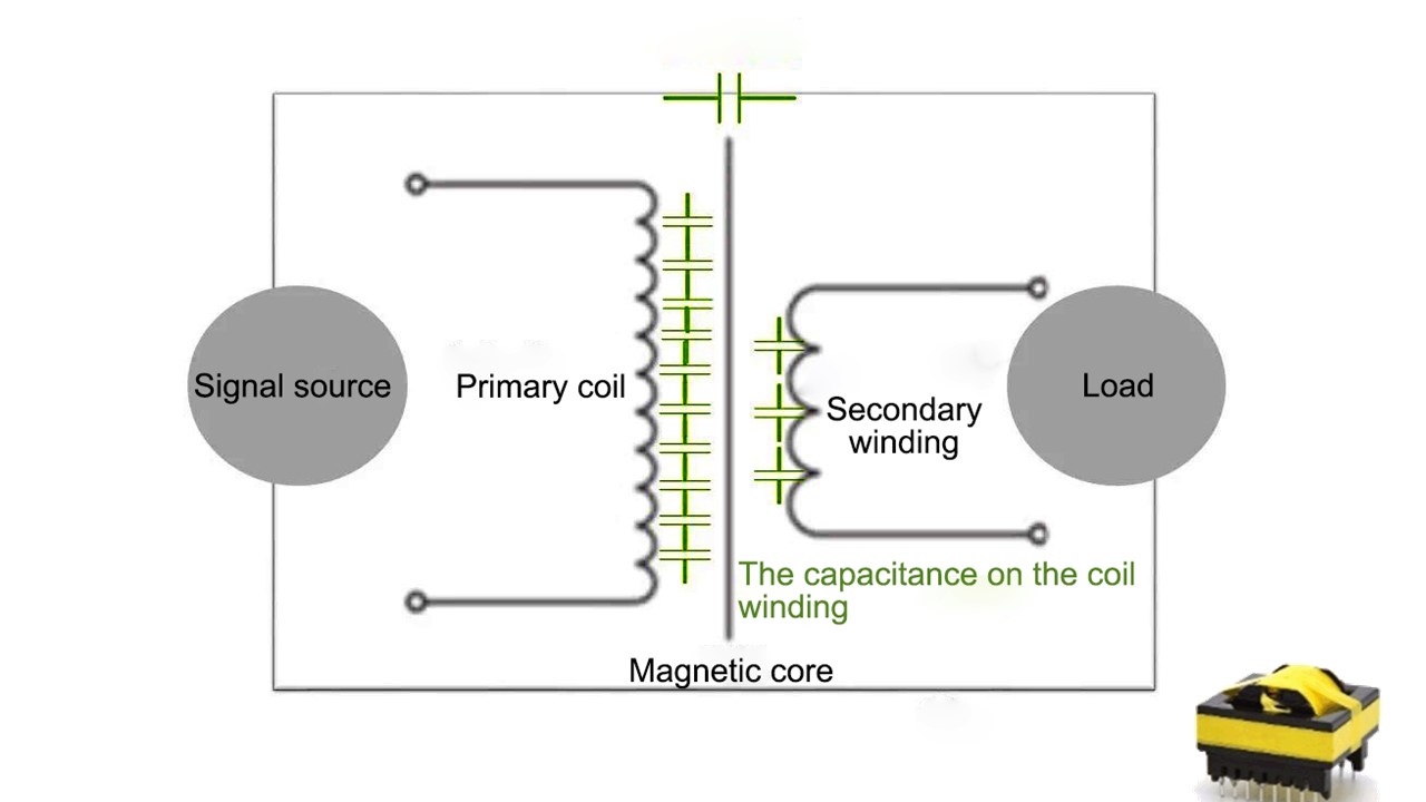
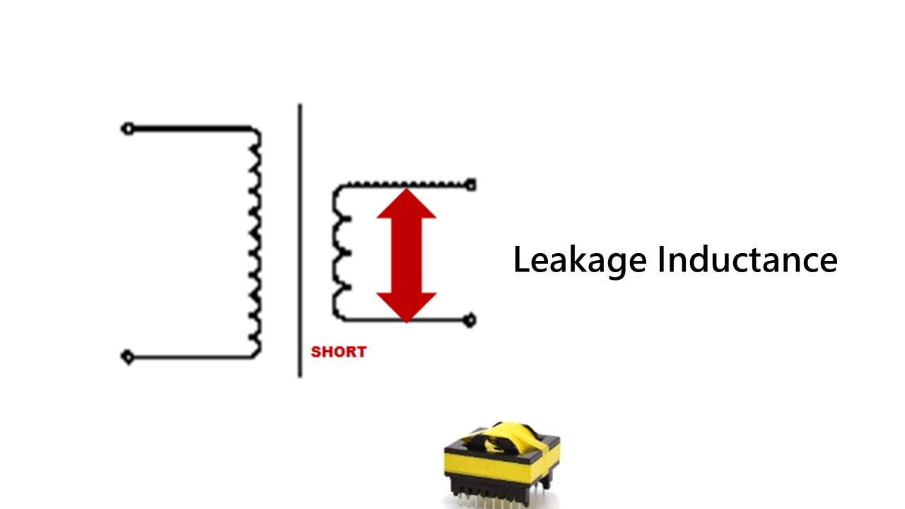
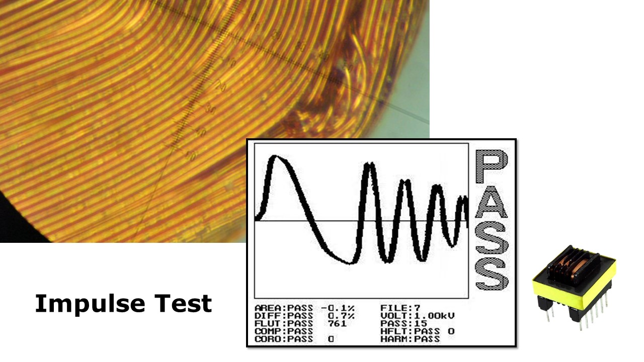
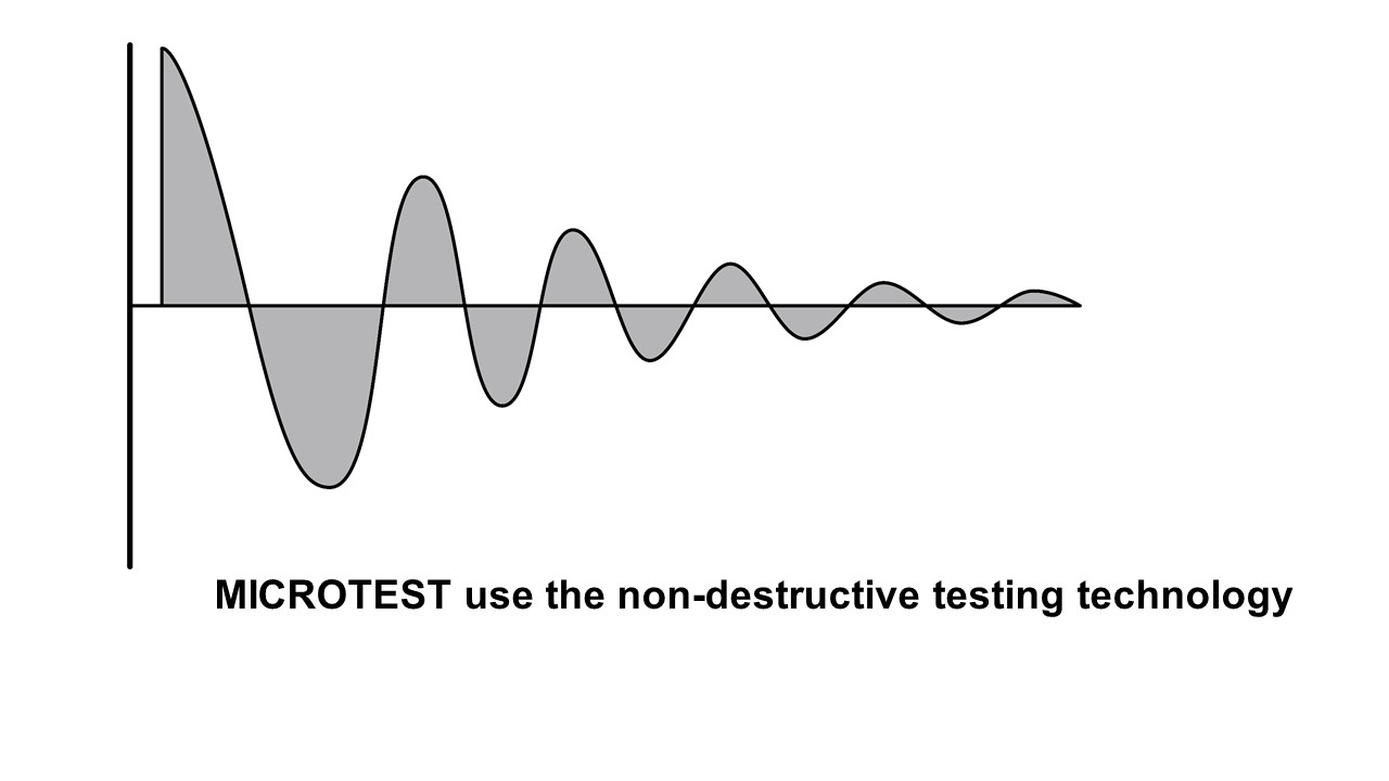
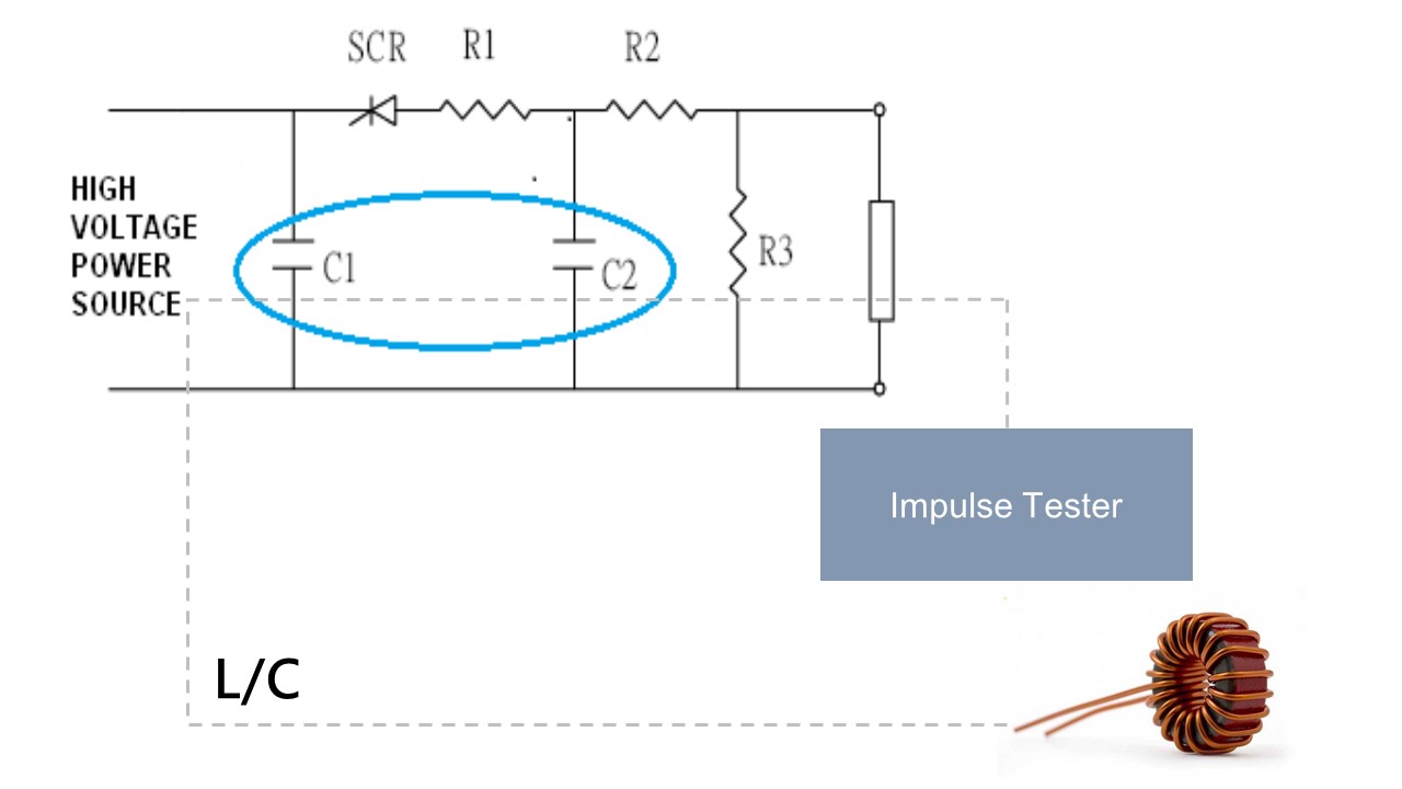
The 9560 test system combines low-voltage testing for transformers with AC/DC withstand insulation testing and interlayer short-circuit testing. The low-voltage testing includes parameters such as inductance value, leakage inductance, DC resistance, AC resistance, quality factor, capacitance value, turns ratio, and checks for shorted terminals. The safety compliance testing offers AC withstand voltage up to 5000V, DC withstand voltage up to 6000V, and maximum insulation impedance of 12000MΩ. The interlayer short-circuit test utilizes non-destructive high-voltage pulse testing technology. It analyzes the damping attenuation waveform generated by L/C resonance to detect short-circuit defects between transformer coils or insulation layers.
SPEC
| Model |
ATP-9560 |
|||||
| Test Channel |
21 |
|||||
| Dynamic Testing For Transformer | ||||||
| Excitation Current | 2mA-4.2A |
Measurement Signal Voltage:0V-310.0Vrms Frequency:45Hz-500Hz |
||||
| Open- circuit voltage | 10V-5000V | |||||
| The no-load power |
0.2-500VA (External AC Source) |
|||||
| Low Voltage Electrical Test | ||||||
| Model | 6265 | 6266 | 6267 | |||
| Frequency | 10Hz-200kHz | 10Hz-500kHz | 10Hz-1MHz | |||
| Frequency Resolution | 5 digits | |||||
| Basic Accuracy | ±0.1% | |||||
| AC Drive Level | 10mV-2Vrms | |||||
| DC Drive Level | 10mV-2V | |||||
| Output Impedance | 100Ω | |||||
| Turn |
Inductance or Voltage Test Freqeuncy:50Hz-200kHz |
|||||
| Test Mode | Meter Mode / List Mode | |||||
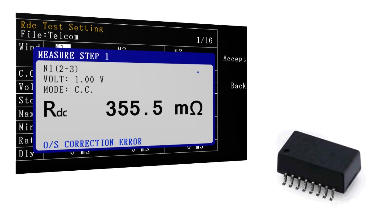
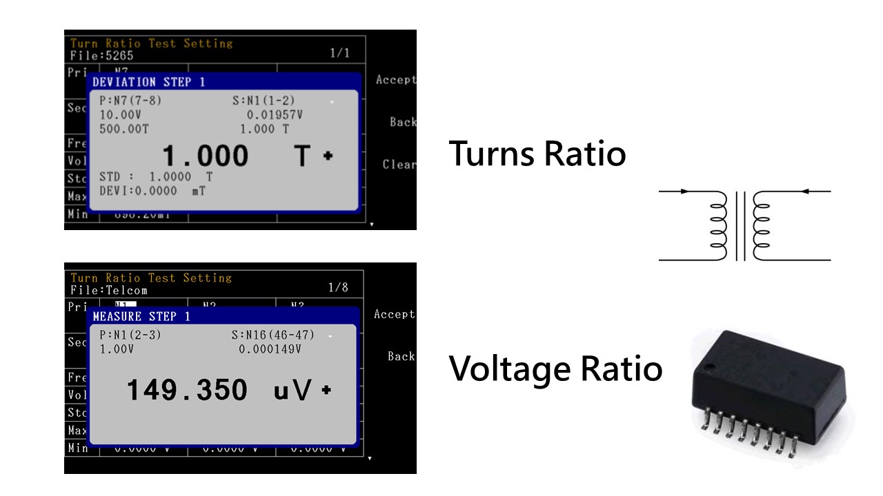
| Parameters Measurement | Inductance (L)、Impedance (Z)、Capacitance (C)、Resistance (R)、Conductance (G)、Susceptance (B)、Admittance (Y)、Alternating Current Resistance (ACR)、Quality Factor (Q)、θ、Direct Current Resistance (DCR)、Leakage Inductance、Turn Ratio、Balance、Short Circuit | |||||
| L, LK | 0.1nH ~ 9999.99H | |||||
| C | 0.00001pF ~ 999.99mF | |||||
| Q,D | 0.00001 ~ 99999 | |||||
| Z,X,R | 0.00001Ω ~ 99.9999MΩ | |||||
| Y | 0.01nS ~ 99.9999S | |||||
| θ | -180°~ +180° | |||||
| DCR | 0.1mΩ ~ 99.999 MΩ | |||||
| Turn | 0.1 ~ 99999.9 turns | |||||
| Pin-Short | 12 pairs, between pin to pin | |||||
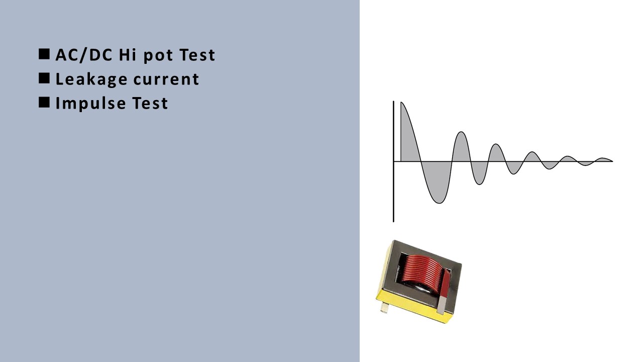
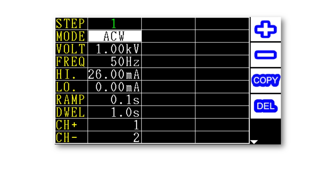
| Hi pot/ Insulation Test | ||||||
| Items | AC Hi pot | DC Hi pot | IR | |||
| Output Voltage | 10V-5000V | 10V-6000V | 10V-1000V | |||
| Voltage Resolution | 1V | 1V | 1V | |||
| Voltage Accuracy | ±(3% of setting+5V) | |||||
| Test Range | 0.001-31mA | 0.001-11mA | 1-12000MΩ | |||
| AC Arcing Detection | 0-20 | 0-10 | - | |||
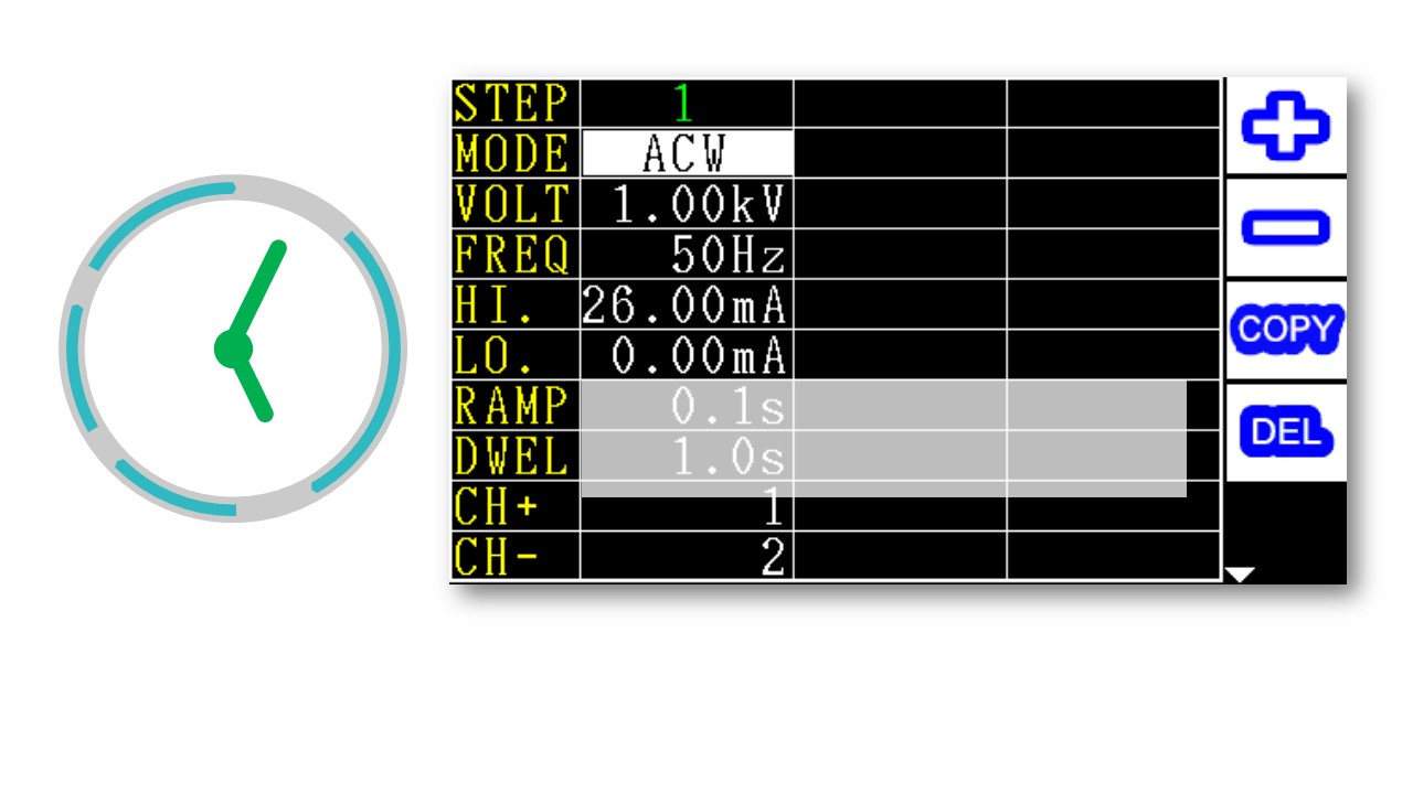
| Measuring time | 0.1-999s | |||||
| Ramp Time | 0.1-10s | |||||
| Time Resolution | 0.1s | |||||
| Impulse Test | ||||||
| Impulse Voltage | 200V-5000V | |||||
|
Area Comparison |
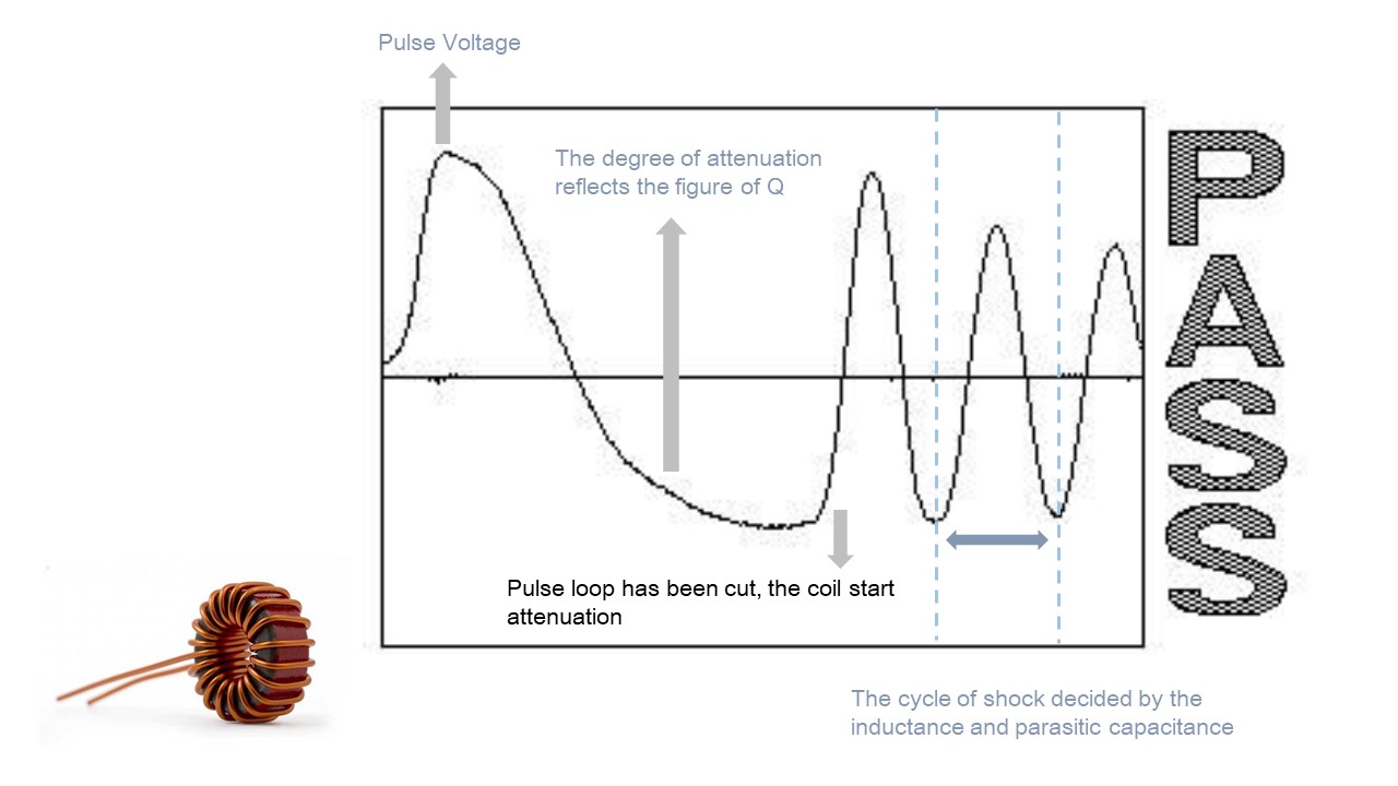
When layer short happened, the loss of power on coil increase, the resonance damping coefficient increase, resonance amplitude decrease, the total area decrease. These are the basic parameters we check layer short. By calculating and comparing the deference of area between golden sample and DUT. |
|||||
|
Area Differential |
Add up the difference between normal wave and DUT wave call “ Area differential”. By calculating and comparing the deference of area between golden sample and DUT. To determine the degree of waveform overlap. |
|||||
|
Waveform Comparison |
Set a acceptable wave range, if the DUT’s wave is in this range shows “pass” otherwise, “fail” |
|||||
| Corona | In pulse test, the insulation defect will cause discharge and create corona. This function is able to count the times that corona happened base on the degree of deviation. Detect the discharge phenomenon on the coil. |
|||||
| Flat |
If the layer short happened, the waveform will tremble. Therefore, the instrument will quantize and compared it. |
|||||
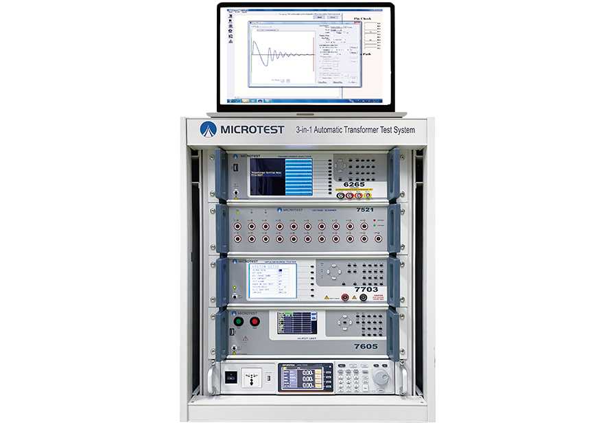
System
| Electronic Rack | |
| Stroage | Unlimited storage (By The PC Link) |
| Power Supply |
Voltage 90Vac-125Vac或190Vac-250Vac Frequency 47-63Hz |
| Power consumption | 1000VA/set |
| Dimension (W*H*D) | 600*1020*1555mm (W*H*D) |
| Weight | 190kg |
| Benchtop Instrument | |||
| Model | Transformer Tester | Impulse Tester | Hi pot Tester |
| 6265/6266/6267 | 7703 | 7605 | |
|
Power Supply |
Voltage 90Vac-125Vac or190Vac-250Vac |
Voltage 115/230Vac±15%
|
Voltage 90Vac-264Vac
|
| Frequency:47-63Hz | Frequency:50/60Hz±5% | Frequency:50/60Hz±5% | |
|
Dimension (W*H*D) |
435x145x522 mm (W*H*D) | 435x190x522 mm | 365x145x430 mm (W*H*D) |
| Weight | 9 Kg | 14kg | 15kg |
| Interface | RS-232、Handler、LAN、USB Host、EXT. I/O | RS-232、Remote、Printer | RS-232、Remote、USB Host、USB Device、EXT.I/O |
| Displa | Color Screen, 7" TFT (800*480) |
5.7" TFT (320*240) |
Color Screen, 4.3" TFT (480*272) |